6commissioning – Lenze E94AYCEC User Manual
Page 39
Lenze · E94AYCEC Communication module (POWERLINK CN) · Communication Manual · DMS 3.0 EN · 08/2014 · TD17
39
6
Commissioning
6.4
Initial switch-on
_ _ _ _ _ _ _ _ _ _ _ _ _ _ _ _ _ _ _ _ _ _ _ _ _ _ _ _ _ _ _ _ _ _ _ _ _ _ _ _ _ _ _ _ _ _ _ _ _ _ _ _ _ _ _ _ _ _ _ _ _ _ _ _
Initial switch-on and diagnosing
1. Switch on the Servo Drive 9400 and check whether it is ready for operation using the
diagnostic LEDs of the communication module.
• Red diagnostic LEDs must not be on.
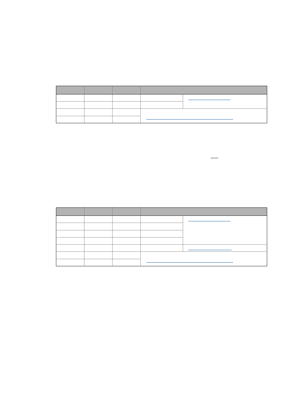
• The following signalling should be visible:
2. If not already done, load the POWERLINK configuration into the Servo Drive 9400.
3. Repeat steps 1. and 2. for all POWERLINK nodes.
4. Start the POWERLINK network.
The network starts automatically if you set the managing node last.
Otherwise there are two options:
• Switch off the network nodes and switch them on together or
• execute a fault reset at the Managing Node (Node ID = ’240’).
5. Check the POWERLINK network again using the diagnostic LEDs of the communication
module.
The following signalling should be visible:
LED
Colour
Status
Meaning
MS
Green
On
Module Status
DE
-
Off
Device Error
X251
Green
On
LED is lit if a connection to the node has been established.
Status displays at the RJ45 sockets (X251, X252) ( 48)
X252
Green
On
LED
Colour
Status
Meaning
MS
Green
On
Module Status
ME
-
Off
Module Error
BE
-
Off
Bus Error
DE
-
Off
Device Error
BS
Green
On
Bus Status
Fieldbus status displays ( 47)
X251
Green
On
LED is lit if a connection to the node has been established.
Status displays at the RJ45 sockets (X251, X252) ( 48)
X252
Green
On