5 powerlink connection, Powerlink connection, Powerlink connection ( 29) – Lenze E94AYCEC User Manual
Page 29: 5installation
Lenze · E94AYCEC Communication module (POWERLINK CN) · Communication Manual · DMS 3.0 EN · 08/2014 · TD17
29
5
Installation
5.2
Electrical installation
_ _ _ _ _ _ _ _ _ _ _ _ _ _ _ _ _ _ _ _ _ _ _ _ _ _ _ _ _ _ _ _ _ _ _ _ _ _ _ _ _ _ _ _ _ _ _ _ _ _ _ _ _ _ _ _ _ _ _ _ _ _ _ _
5.2.5
POWERLINK connection
• The POWERLINK is wired using the two RJ45 sockets X251 and X252.
• If possible, do not wire more than 10 nodes in a row in a network line.
• In case of more than 10 nodes you should deactivate the automatic calculation of the hub level
in the »Engineer« and enter it manually to increase the performance.
• With a cycle time of 1 ms, 25 nodes can be operated.
The number of nodes can be increased if the POWERLINK cycle time is increased as well.
• You can use a standard Ethernet patch cable to connect the communication module to the
POWERLINK fieldbus.
• The installation and removal of the Ethernet cables is optimised for the use of connectors in
accordance with the "Automation Initiative of German Domestic Automobile Manufacturers"
(AIDA).
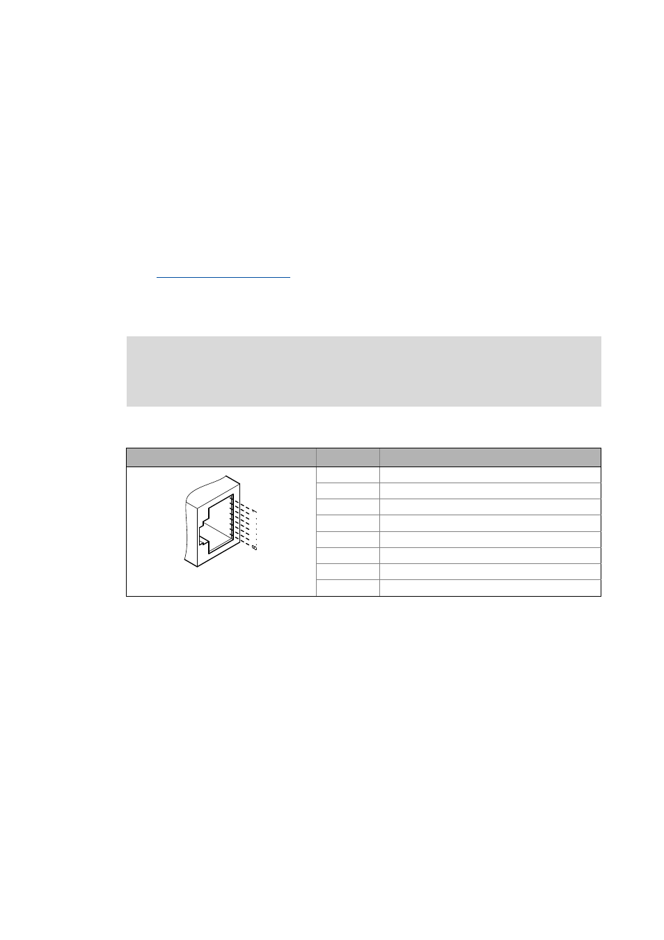
Pin assignment of the RJ45 sockets
Tip!
The POWERLINK interfaces feature an auto-MDIX function. This function adjusts the
polarity of the RJ45 interfaces so that a connection can be established irrespective of the
polarity of the opposite POWERLINK interface and irrespective of the type of cable used
(standard patch cable or crossover cable).
Note!
To prevent the RJ45 socket from being damaged, insert or remove the Ethernet cable
connector straight (at a right angle) into or from the socket.
RJ45 socket
Pin
Signal
E94AYCXX004C
1
Tx +
2
Tx -
3
Rx +
4
-
5
-
6
Rx -
7
-
8
-