6 commissioning of profibus, 1 overview of the commissioning steps, Commissioning of profibus – Lenze PROFIBUS Controller-based Automation User Manual
Page 25: Overview of the commissioning steps, 6commissioning of profibus
Lenze · Controller-based Automation · PROFIBUS® Communication Manual · DMS 4.3 EN · 04/2014 · TD17
25
6
Commissioning of PROFIBUS
6.1
Overview of the commissioning steps
_ _ _ _ _ _ _ _ _ _ _ _ _ _ _ _ _ _ _ _ _ _ _ _ _ _ _ _ _ _ _ _ _ _ _ _ _ _ _ _ _ _ _ _ _ _ _ _ _ _ _ _ _ _ _ _ _ _ _ _ _ _ _ _
6
Commissioning of PROFIBUS
This chapter provides information on how to commission the Lenze automation system with
PROFIBUS.
Depending on the field devices used, the following
are required:
• »EASY Starter«
• »Engineer«
• »PLC Designer«
6.1
Overview of the commissioning steps
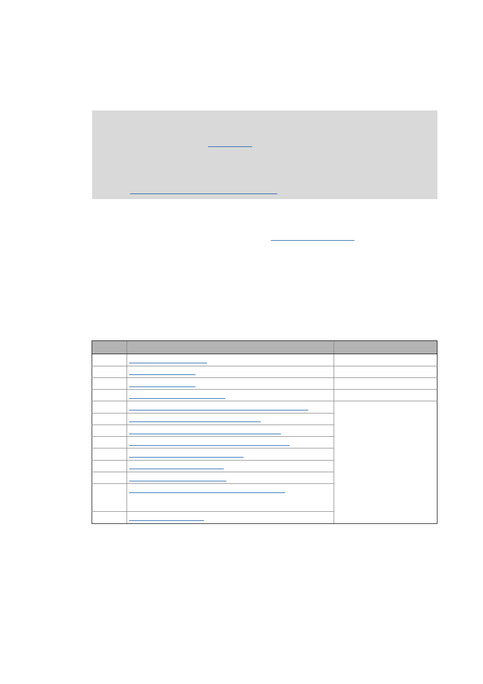
The main commissioning steps are listed in the following table:
Note!
Via PROFIBUS only Logic
can be operated in the Lenze automation
system.
Inverters which are to be controlled via the central Motion functionality must always be
connected via EtherCAT.
Mixed operation PROFIBUS with EtherCAT
Step
Activity
Software to be used
1.
Planning the bus topology ( 26)
2.
3.
4.
Commissioning the field devices ( 27)
»Engineer« / »EASY Starter«
5.
Creating a PLC program with a target system (Logic/Motion) ( 28)
»PLC Designer«
6.
Configuring the communication parameters ( 30)
7.
Importing missing devices / device description files ( 32)
8.
Creating a control configuration (adding field devices) ( 33)
9.
Configuration of the PROFIBUS master ( 37)
10.
Configuring the PROFIBUS slave ( 40)
11.
Compiling the PLC program code ( 41)
12.
Logging in on the controller with the »PLC Designer« ( 41)
With the log-in, the fieldbus configuration and the PLC program are
loaded into the Controller.
13.