2 basic wiring of profibus, Basic wiring of profibus, 4the lenze automation system with profibus – Lenze PROFIBUS Controller-based Automation User Manual
Page 17: 12 3 r s s r
Lenze · Controller-based Automation · PROFIBUS® Communication Manual · DMS 4.3 EN · 04/2014 · TD17
17
4
The Lenze automation system with PROFIBUS
4.1
Brief description of PROFIBUS
_ _ _ _ _ _ _ _ _ _ _ _ _ _ _ _ _ _ _ _ _ _ _ _ _ _ _ _ _ _ _ _ _ _ _ _ _ _ _ _ _ _ _ _ _ _ _ _ _ _ _ _ _ _ _ _ _ _ _ _ _ _ _ _
4.1.2
Basic wiring of PROFIBUS
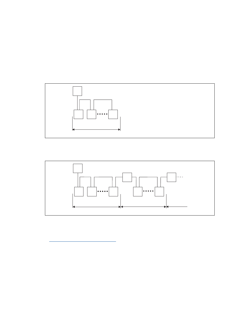
Two simple RS485 networks are described in the following examples.
Each segment of the network must be terminated at both ends. The bus terminators of the
PROFIBUS are marked with a "Z" in each one of the following examples.
In the case of an RS485 network consisting of only one segment, the network starts at the PROFIBUS
master (M) with the integrated bus terminating resistor and ends at the last PROFIBUS station (S);
its bus terminating resistor in the bus connector must be activated.
[4-2]
PROFIBUS network with one segment
A PROFIBUS network consisting of several segments contains repeaters (R) for connecting the
segments. The repeaters are provided with integrated bus terminating resistors.
[4-3]
PROFIBUS network with repeaters
If you do not use a repeater at the end of the segment, the bus terminating resistor in the bus
connector of the last device must be activated.
Activating the bus terminating resistor
E94YCPM012a
M
Z
Z
S
S
S
1
E94YCPM012b
M
Z
Z
S
S
S
Z
Z
Z
Z
1
2
3
R
S
S
R