1 structure of the profibus system, Structure of the profibus system, 4the lenze automation system with profibus – Lenze PROFIBUS Controller-based Automation User Manual
Page 15
Lenze · Controller-based Automation · PROFIBUS® Communication Manual · DMS 4.3 EN · 04/2014 · TD17
15
4
The Lenze automation system with PROFIBUS
4.1
Brief description of PROFIBUS
_ _ _ _ _ _ _ _ _ _ _ _ _ _ _ _ _ _ _ _ _ _ _ _ _ _ _ _ _ _ _ _ _ _ _ _ _ _ _ _ _ _ _ _ _ _ _ _ _ _ _ _ _ _ _ _ _ _ _ _ _ _ _ _
4.1.1
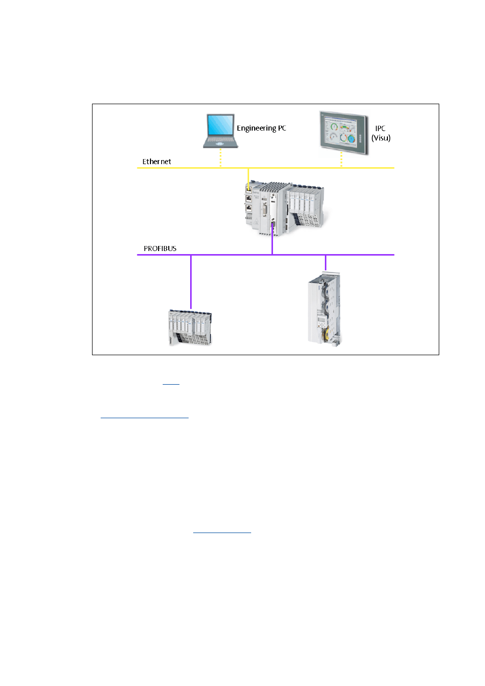
Structure of the PROFIBUS system
[4-1]
Example: PROFIBUS with the 3231 C Lenze Controller (I/O system 1000 and Servo Drive 9400 as slaves)
In the example (Fig.
), the 3231 C Lenze Controller is the PROFIBUS master. It can communicate
with one or several stations (slaves).
PROFIBUS has an internal line topology (without repeater) or a tree topology (with repeater).
The PROFIBUS network must be terminated at the first and last station. The bus terminating resistor
is integrated into the bus connector and is activated by a switch.
Using the Lenze Controller as a PROFIBUS slave
Using the MC-PBS communication card, the Lenze Controllers can also be applied as PROFIBUS
slaves.
Tip!
A sample project for operation of a 3200 C controller as PROFIBUS slave can be found in the
"Download" area at
:
Application Knowledge Base: All articles Application Ideas Pool Controller 3200 C