Figure 3-8: lift assist wheel installation, Lift assist wheel, Warning – Landoll 2000 Series Row Crop Cultivator User Manual
Page 20
3-10
F-140-0512 Edition
ASSEMBLY INSTRUCTIONS
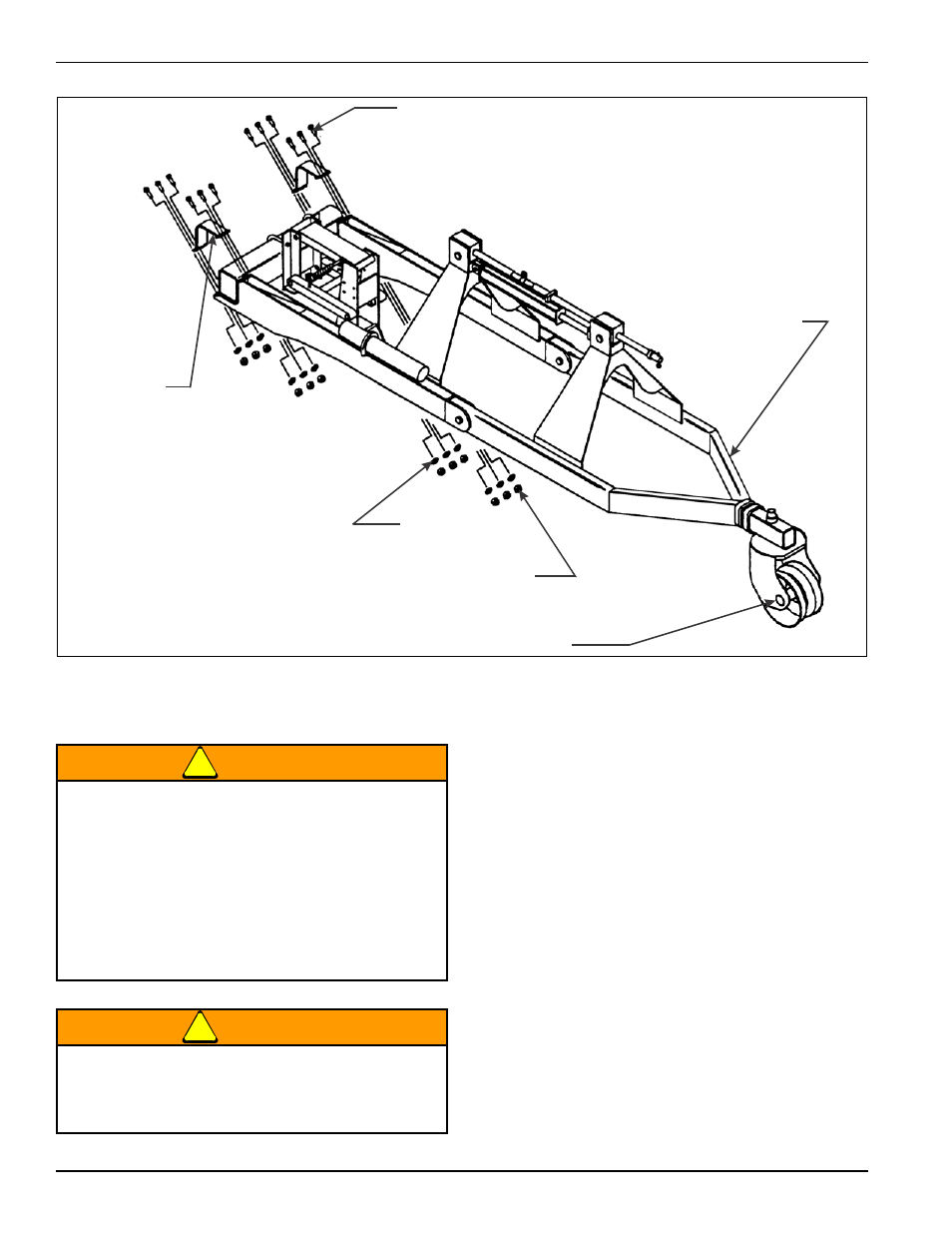
Figure 3-8: Lift Assist Wheel Installation
Lift Assist Wheel
WARNING
WARNING
1.
Place the base of the lift assist wheel frame against
the main frame bar, straddling (on both sides of) the
center tool frame assembly. Secure the assist wheel
using the mounting brackets, 5/8-11 X 3 hex head
cap screws, lock washers, and hex nuts that come
with the lift assist wheel (See Figure 3-8.)
2.
Coupling hoses are to be owner-supplied. They
should be long enough to allow lifting or lowering of
the cultivator without stretching the hoses. Be sure to
set the hoses so not to interfere with the operation of
the cultivator. Once set, secure the hoses with tie
wraps.
5/8-11 X 3 HEX
HEAD CAP SCREW
5/8-11 SPLIT
LOCK WASHER
5/8-11 HEX NUT
LIFT ASSIST WHEEL
MAIN FRAME
MOUNTING
BRACKET
lift assist wheel op
An escaping hydraulic oil under pressure can
produce enough force to penetrate the skin,
causing serious personal injury. Before applying
pressure to the system, be sure all connections
are tight and that lines, pipes, and hoses are not
damaged before disconnecting lines, be sure to
relieve all pressure. Hydraulic oil escaping from a
very small hole can be almost invisible. Use a
piece of cardboard or wood, not your hands, to
search for suspected leaks.
If injured by escaping hydraulic oil, see a doctor
at once. Serious infection or reaction can develop
if proper medical treatment is not administered
immediately.