Figure 3-1: hydraulic installation, Wing fold plumbing installation – Landoll 2000 Series Row Crop Cultivator User Manual
Page 12
3-2
F-140-0512 Edition
ASSEMBLY INSTRUCTIONS
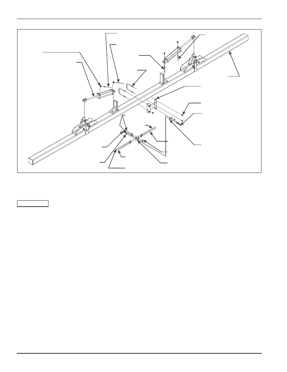
Figure 3-1: Hydraulic Installation
Wing Fold Plumbing Installation
IMPORTANT
See Figure 3-1 and Table 3-1 for parts names. When
assembly is done, tighten all fastening hardware to
the torques listed in Table 2-1 and Table 2-2. Tighten
u-bolts evenly to show an even amount of thread on
both legs of the u-bolt.
1.
Assemble the base of each cylinder to a cylinder
base mount. Secure each with a clevis pin and the
hairpin clips that come with the cylinders. Be sure the
cylinders are set with the hose ports on the top when
installation is done.
2.
Assemble the rod end of each cylinder to the top of
the inner hinge arms. Secure each with the clevis
pins and the hairpin clips given with the cylinders.
3.
Install the hydraulic manifold mounting bracket on
the upper leg of the left-hand U-bolt on the center
tool frame (See Figure 3-1.)
4.
Assemble the hydraulic manifold to the manifold
mounting bracket using bolts and nuts provided (See
Figure 3-1.)
5.
Insert Hose B with a 90° fitting to the base end of the
left-hand cylinder. Insert the other end to the bottom
hole in the left-hand side of the hydraulic manifold.
6.
Insert Hose A with a 90° fitting to the rod end of the
left-hand cylinder. Insert the other end of the hose to
the top hole in the left-hand side of the hydraulic
manifold.
7.
Insert Hose D with a 90° fitting to the base end of the
right-hand cylinder. Insert the other end to the bottom
hole in the right-hand side of the hydraulic manifold.
8.
Insert Hose E with a 90° fitting to the rod end of the
right-hand cylinder. Insert the other end of the hose
to the top hole in the right-hand side of the hydraulic
manifold.
9.
Insert coupling Hoses C (2 hoses supplied - 48" long
on all models, coupler fittings are owner supplied) to
the holes in the front of the hydraulic manifold.
Connect the coupler fittings to the tractor.
10. Lift the cultivator clear of the stands. Leave the
stands under the main frame bar to prevent
accidental lowering.
11. Cycle the wing fold through several cycles to
completely charge the hoses and cylinders with
hydraulic oil. The hydraulic system must be free of air
to keep movement of the wings in control during
folding or unfolding. Add oil as needed to the tractor
hydraulic system.
2mc809-010082 op
90º RESTRICTOR
FITTING
HYDRAULIC CYLINDER
HOSE B
HOSE A
HOSE D
TOOL MOUNT
U-BOLT
TOOL BAR
TOOL FRAME
MOUNTING ANGLE
3/4-10 HEX LOCK NUT
1/2-13 X 3-1/2 HEX
HEAD CAP SCREW
HYDRAULIC MANIFOLD
MOUNTING BRACKET
HOSE E
HOSE C
HOSE E
HOSE A
HOSE B
HOSE D
PLUG
HYDRAULIC
MANIFOLD
1/2-13 HEX
LOCK NUT
1/2 FLAT
WASHER