Figure 3-5: coulter blade installation, Coulter blade installation – Landoll 2000 Series Row Crop Cultivator User Manual
Page 17
ASSEMBLY INSTRUCTIONS
3-7
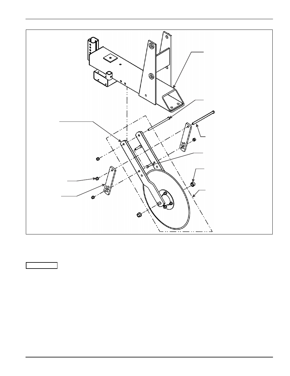
Figure 3-5: Coulter Blade Installation
Coulter Blade Installation
IMPORTANT
See Figure 3-5 for parts names. When assembly is
done, tighten all fastening hardware to the torques
listed in Table 2-1 and Table 2-2. Tighten u-bolts
evenly to show an even amount of thread on both
legs of the u-bolt.
1.
Loosely assemble a coulter brace to the outer sides
of each coulter fork with 1/2-13 X 2 hex head cap
screws and hex lock nuts (Figure 3-5 shows proper
mounting position.)
2.
Loosely assemble each coulter fork assembly to a
tool frame with a 1/2-13 X 8 hex head cap screw
inserted through the coulter fork side, the tool frame,
and the other coulter fork side, secured with a locking
nut (Figure 3-5 shows proper mounting position.)
3.
Loosely attach the coulter braces to the tool frames
by inserting a 1/2-13 X 8-1/2 hex head cap screw
through one brace, the tool frame, and through the
other brace. Secure them with 1/2-13 hex lock nuts.
4.
Leave all attaching hardware loose until final
adjustments are made (See “Initial Setup” on
page 4-3 for operation and maintenance
procedures.)
COULTER FORK
PLATE
1/2-13 HEX
LOCK NUT
COULTER
BRACE
TOOL MOUNT FRAME
1/2-13 X 8 HEX
HEAD CAP SCREW
1/2-13 X 8-1/2 HEX
HEAD CAP SCREW
1/2-13 X 2 HEX
HEAD CAP SCREW
3/4-10 HEX LOCK NUT
COULTER FORK
ASSEMBLY
545m104383 op