Figure 3-3: gauge wheel installation, Gauge wheel installation – Landoll 2000 Series Row Crop Cultivator User Manual
Page 15
ASSEMBLY INSTRUCTIONS
3-5
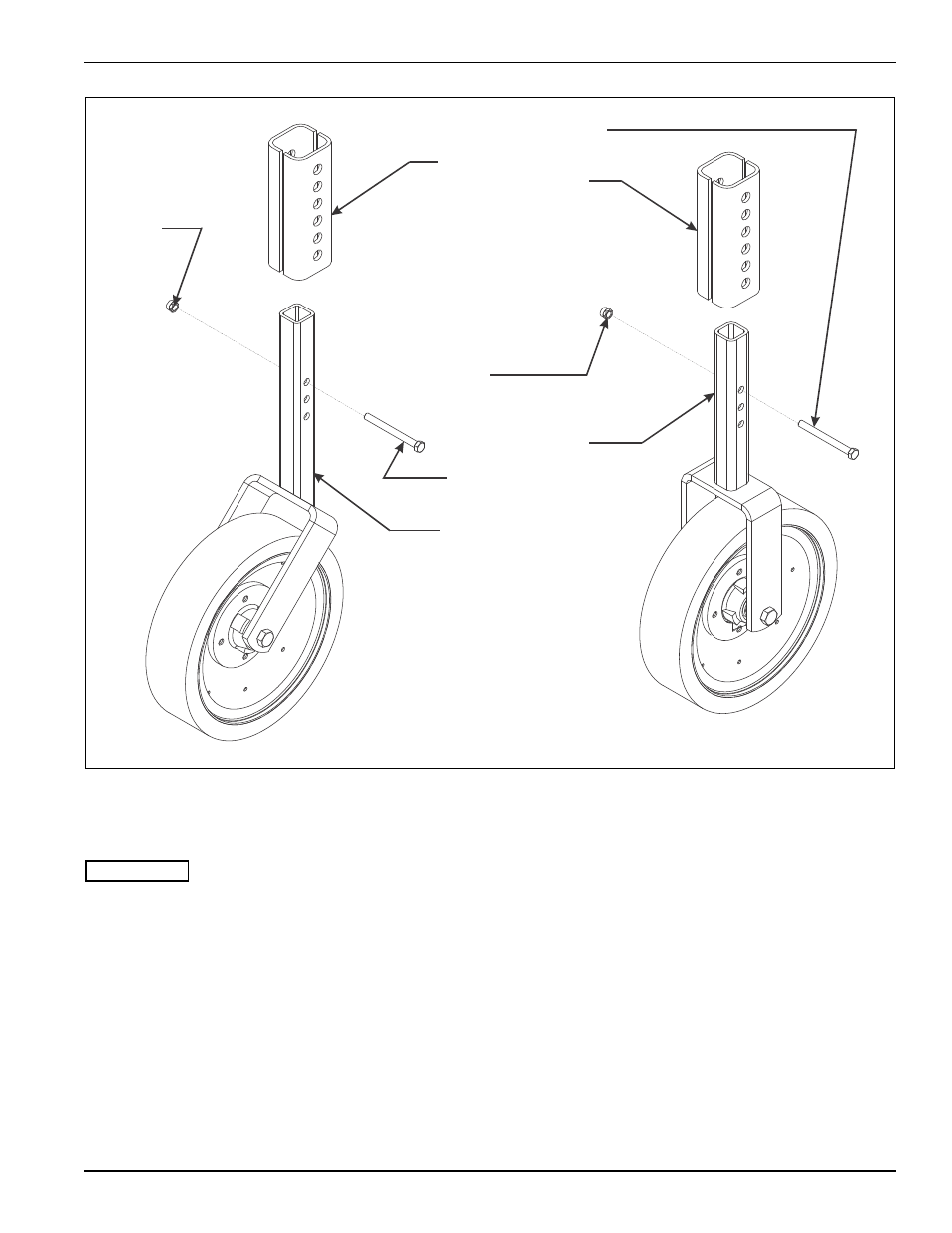
Figure 3-3: Gauge Wheel Installation
Gauge Wheel Installation
IMPORTANT
See Figure 3-3 for parts names. When assembly is
done, tighten all fastening hardware to the torques
listed in Table 2-1 and Table 2-2. Tighten u-bolts
evenly to show an even amount of thread on both
legs of the u-bolt.
1.
Find the end gauge wheel assemblies with the 45°
angle mounting forks.
2.
Remove the 1/2-13 X 3-1/2 hex head cap screw and
serrated flange head nut from the gauge wheel
brackets. These are on the front of the outer tool
frames.
3.
Slide a gauge wheel square tube up through the
bracket on each outer tool frame with the forks
pointing forward. Position the gauge wheel for proper
depth. Use the 1/2-13 X 3-1/2 hex head cap screw
and serrated flange head nut to position the gauge
wheel. Tighten the nut until wheel tube is securely
clamped into place.
4.
The remaining middle gauge wheel assemblies are
installed on the inner tool frames. They are installed
using the steps described in steps 2 through 3.
TOOL MOUNT
FRAME BRACKET
1/2-13 FLANGE
HEAD SERRATED
NUT
1/2-13 X 3-1/2 HEX
HEAD CAP SCREW
MIDDLE GAUGE
WHEEL ASSEMBLY
(INNER FRAMES)
1/2-13 X 3-1/2 HEX
HEAD CAP SCREW
END GAUGE
WHEEL ASSEMBLY
(OUTER FRAMES)
2000 gauge wheel assembly
1/2-13 FLANGE
HEAD SERRATED
NUT