Variable ratio adjustment, Figure 4-6: variable ratio leveler adjustment – Landoll 2111 Coulter Chisel User Manual
Page 74
4-6
F-719-0413 Edition
OPERATION AND MAINTENANCE
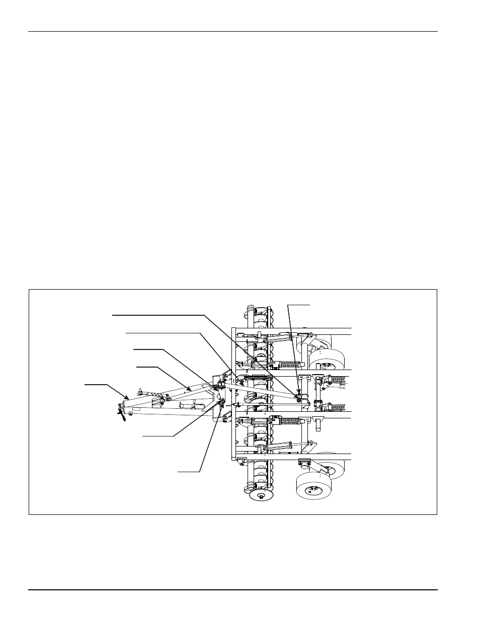
Variable Ratio Adjustment
The leveler is equipped with a variable ratio adjustment.
This is located at the rear of the hitch and at the center of
the wheel lift where the leveler tube attaches. Connect
the leveler tube to the top hole in the center lift and the
bottom hole in the tongue for normal operation. This will
cause the rear of the machine to raise higher than the
front increasing transport height. The lower hole on the
center lift provides an increased leveler ratio, which will
cause the Coulter Chisel to become more level in
transport. The lower hole should be used when a rear
tow hitch is needed to reduce the height of the rear tow
hitch during transport.
The adjustments can be set as follows:
• Top hole in center lift, top hole in tongue - this will
raise the rear of the machine the highest.
• Top hole in center lift, bottom hole in tongue - normal
operation.
• Bottom hole in center lift, top hole in tongue - normal
operation with a tow hitch
• Bottom hole in center lift, bottom hole in tongue - to
lower rear tow hitch if needed.
1.
To change the variable ratio adjustment, lower the
implement to the ground and relieve the load on the
lift system.
2.
Extend or retract the radius rod, until the load is
removed from the leveler tower.
3.
Remove the 1-1/4-7 x 9-1/2 hex head cap screw,
slotted lock washer, and hex nut through the leveler
tower and hitch (See Figure 4-6.)
4.
Reinstall the 1-1/4-7 x 9-1/2 hex head cap screw,
slotted lock washer, hex nut, and leveler tower in the
desired position. The radius rod will require some
adjustment to connect to the new position.
5.
To adjust the leveler tube at the center lift, remove
the hitch pin, 1/2 x 2-1/4 slotted spring pin, and 1-8
hex lock nut.
6.
Reinstall the hitch pin, 1/2 x 2-1/4 slotted spring pin,
1-8 hex lock nut in the leveler tube at the center lift in
the desired position.
Figure 4-6: Variable Ratio Leveler Adjustment
HITCH PIN, 1/2 X 2-1/4
SLOTTED SPRING PIN,
AND 1-8 HEX LOCK NUT
ADJUSTMENT HOLES ON
WHEEL LIFT
HOLES ON TONGUE
LEVELER TUBE
LEVELER TOWER
HITCH RADIUS ROD
HITCH
1-1/4-7 x 9-1/2 HEX HEAD
CAP SCREW, SLOTTED
LOCK WASHER, AND HEX NUT
2110 var adj ratio