Electric clutch – Landoll SL/SLB/SLP/SLPB/SLPB TURFMAKER III User Manual
Page 27
ASSEMBLY INSTRUCTIONS
2-17
Electric Clutch
1.
Check that the clutch case has proper clearance
between rubber bumper stop. Improper clearance
may prevent clutch from engaging or cause it to
disengage. See Figure 2-21.
Figure 2-21: Clutch Case Clearance
2.
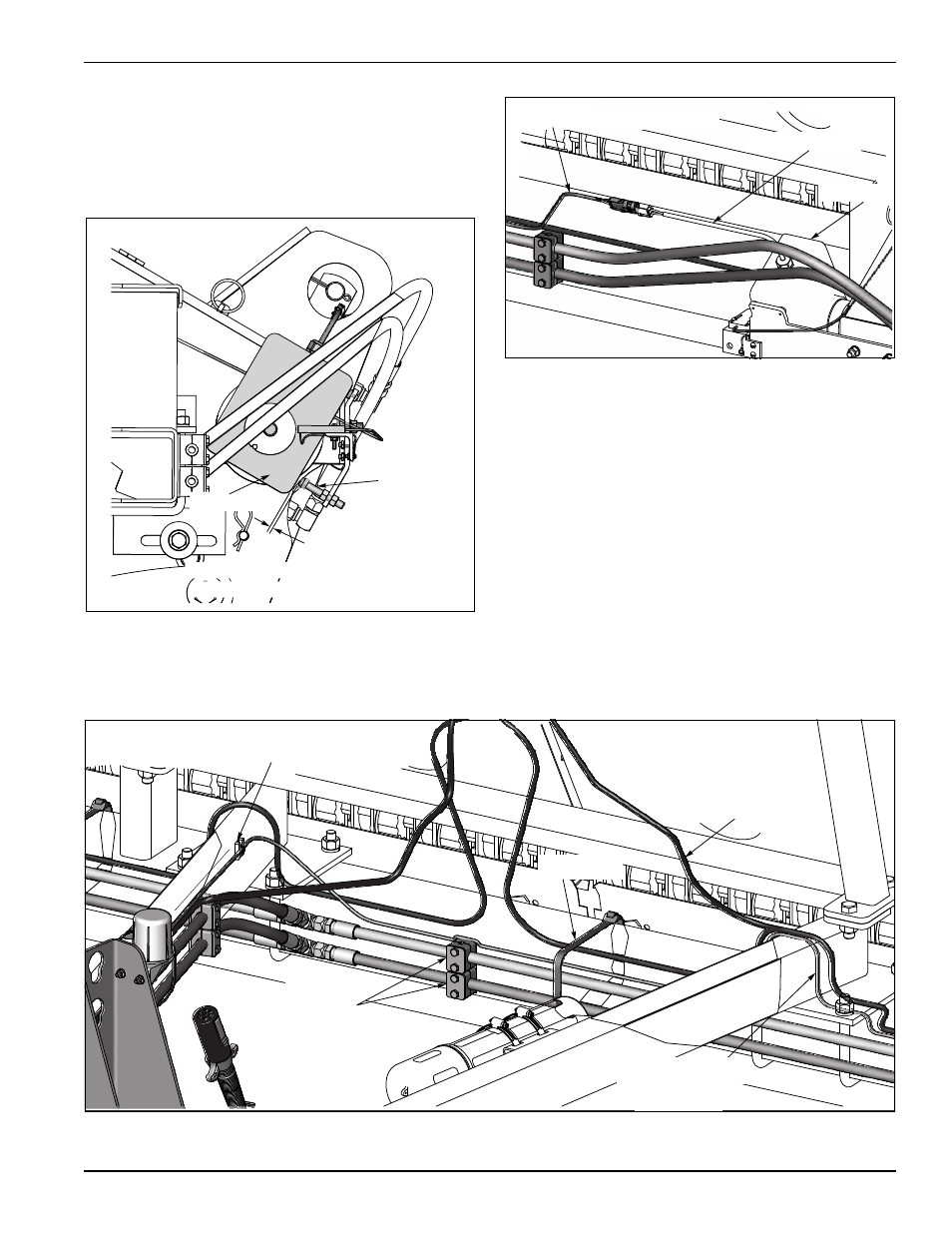
Connect the clutch wiring harness to clutch lead and
route wire along frame and drawbar. See
Figure 2-22.
Figure 2-22: Clutch Lead
3.
Secure to the frame and drawbar. Run along with
hydraulic hoses and warning light harness. Use cable
ties or adhesive mounts. See Figure 2-23.
4.
Install the switch onto the tractor in a convenient
location with the hook and loop provided or other
type of mount (not included).
5.
Attach the wire lead to the power source and secure
wire.
6.
Check clutch operation. Clutch will disengage when
power is applied. (Clutch will make a clicking sound).
Set seeder on the ground and drive a short distance.
While driving turn the switch “on” and “off”.
7.
Turn the switch to the “ON” position when the seeder
is not used to shut off power to prevent possible
overheating of clutch coil.
Figure 2-23: Secure Wiring to Frame
1/8” Gap
Clutch
Bumper Bolt
Clearance From
Bumper Stop
CLUTCH LEAD
CLUTCH
CLUTCH WIRING HARNESS
Adhesive Mount
Cable Tie
Warning Light
Harness
Clutch Wiring
Harness
Hoses &
Hose Clamps