5 system bus, System bus, 6 electrical connection – JUMO 705040 mTRON T - Router Module Operating Manual User Manual
Page 59
59
6 Electrical connection
6.5
System bus
Side system bus
The side system bus connects the base unit or router module to the input/output modules ar-
ranged on the same DIN rail.
Either
•
a base unit or
•
a router module
must always be installed on the left, at the start of the DIN rail. The distinguishing feature is that
their plug-in connections are only to the right; all other modules have plug-in connections on
both sides.
The system bus on the side is physically implemented as a point-to-point connection. The con-
nection is only ever made between two neighboring modules. If a module or a module insert
does not function or is removed, the modules to the right can no longer be reached.
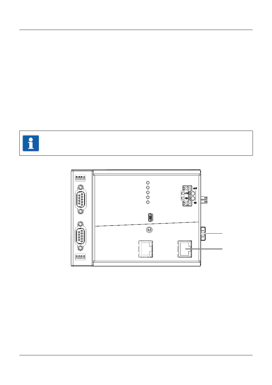
System bus connections of a base unit, using the example of a central processing unit
The router module has an identical connection for the side system bus, but a total of three RJ45
sockets for connecting to the base unit (Bus In), the multifunction panel, or additional router
modules (Bus In, Bus Out1, Bus Out2).
NOTE!
The further to the left a module is installed, the greater the probability that the module can still
be reached in the event that a different module fails.
Setup
LAN
Bus Out
Run
Stop
Reset
Power
Status
Bus Error
Com1
Com2
Com2
2
1
3
4
ON
2
1
3
4
ON
Com1
3
7
3
Side system bus Out
7
System bus Out