2 module sequence, 1 system with centralized module assignment, Module sequence – JUMO 705040 mTRON T - Router Module Operating Manual User Manual
Page 32: 5 installation
5 Installation
32
5.2
Module sequence
5.2.1
System with centralized module assignment
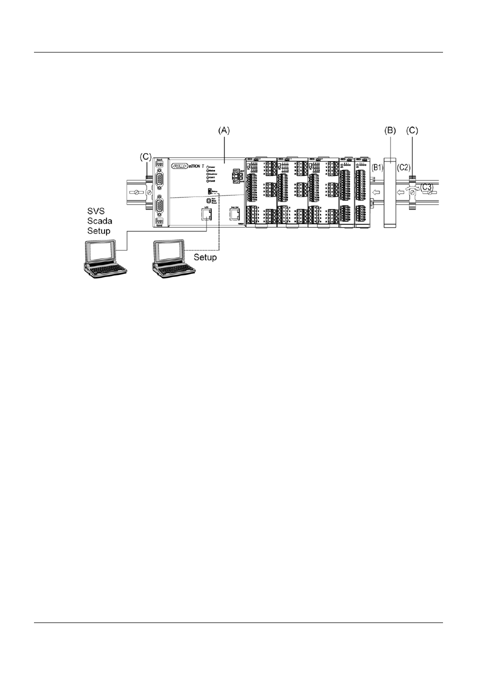
Example: Central processing unit with input/output modules
The central processing unit (A) is required for this purpose. It contains all configuration, param-
eter, and process data of the entire system and the customer-specific PLC application (if appli-
cable). All modules are mounted to the right; the sequence is at the user's discretion. They are
snapped on to the DIN rail and moved to the left against the central processing unit or the pre-
vious module until the plug connections for the voltage supply and the system bus are connect-
ed. Any distance between two modules is not allowed.
A maximum of 30 input/output modules can be managed by one central processing unit.
Cover
Once all modules are installed the cover (B) must be positioned on the DIN rail from the right
and moved to the left against the final module (B1). It protects the contacts of the final module
against touching and contamination.
The cover is included in the scope of delivery of the central processing unit and therefore does
not need to be ordered separately.
End brackets
The final mechanical element of the DIN rail is formed by an end bracket (C) on each side. The
right end bracket is positioned on the DIN rail from the outside, moved to the left against the
cover (C2), and fastened with a screwdriver (C3). The left end bracket is mounted according to
the same principle following the installation of the central processing unit.
The end brackets are included in the scope of delivery of the central processing unit and there-
fore do not need to be ordered separately.