JULABO FPW50-HL Refrigerated Circulators User Manual
Page 19
HL
19
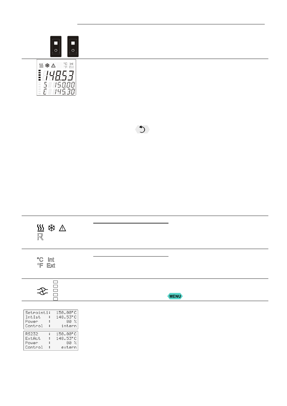
1a
1b
Mains power switch, illuminated for circulator
Mains power switch, illuminated for cooling machine
2
VFD COMFORT-DISPLAY
Header: Control indicators
Line 1: Actual value
internal or external
The display is depending on the selected control mode in the
menu > Control < (internal or external).
Line 2: Working temp. setpoint, constantly S xxx.xx
Line 3: Actual value (E = external or I = internal)
Alternating with the display in line 1
Use the keys
to indicate further values in line 3
PI
Capacity in % - with manipulated variable set to >control<*
PS Capacity in % - with manipulated variable set to >serial<* or
>eprog<*
H
Heater capacity in Watts
U
Mains voltage Volts
F
Flow rate in liters/minute
(providing EPROG input set to >Flow rate<)
*refer to >MENU / CONFIGIGURATIO> page 37
2.1
Control indicators in the header:
Heating / Cooling / Alarm /
R
emote control
2.2
Control indicators in the header:
Temperature indication Internal or External actual value
Temperature indication in °C or °F
2.3
Display for the adjusted pump pressure stage in the -OFF- mode.
Display for the effective pump pressure stage (rotation speed) after start.
Four stages, adjustable via the
button, in the menu >PUMP<.
3
LCD DIALOG-DISPLAY
Line 1: Setpoint and origin of setpoint programming
(Key / RS232 or RS485 / ext. Pt100 / EProg)
Line 2: Actual value - internal or external,
identical to line 1 of the VFD-COMFORT-DISPLAY
Line 3: Heating capacity in %.
Line 4: Control type: internal / external