INFICON MDC-370 Thin Film Deposition Controller User Manual
Page 148
MDC-370 DEPOSITION CONTROLLER
26. Receive Output setup (Code #25)
Instructs the controller to enter the incoming Output parameters for Output #n into
memory. A description of the Output parameter list is given above.
Format: Header, Address, Instruction=25, Length=45,Output #(0-15), 2 byte
Type, 16 byte Name, 24 byte Condition string,1 byte Card#, 1 byte pin#,
Checksum
27. Send Action setup (Code #26)
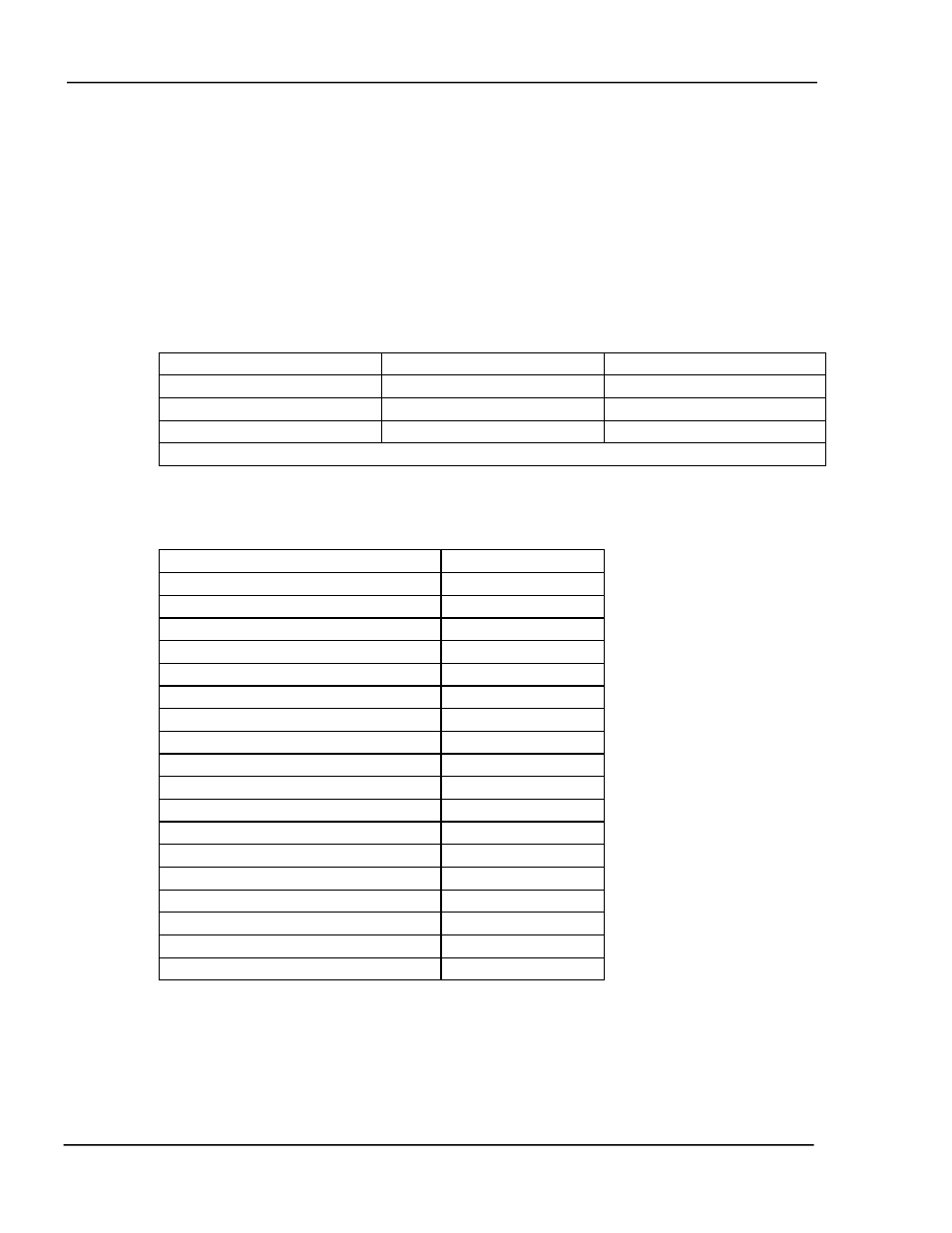
Instructs the controller to send the Action parameter list for Action #n. A
description of the Action parameter list is as follows:
Parameter Name
Length (bytes)
Allowable Range
Action #
1
(0-15)
Action Type
1
(0-20)
Condition String
24
! | & ( )
Total 26 bytes
Format: Header, Instruction=26, Length=1, Action #(0-15), Checksum
The action type defines the action that will be taken when the condition is
evaluated as true. The following table contains the list of possible actions.
Action Name
Action Type
No Action
0
Manual Power
1
Zero Thickness
2
Reset Process
3
Abort Process
4
Halt Process
5
Terminate Deposit
6
Hold In State
7
Step From State
8
Sound Attention
9
Sound Alert
10
Sound Alarm
11
Start Process
12
Select Process 1-8
13-20
Switch Crystals
21
Start Timer #1-8
22-29
Start Timer #1-8
22-29
Set Softnode #1-8
30-37
Example: To instruct the controller to send the Action setup parameter list for
Action #14 the computer would send:
Chr$(255)+Chr$(254)+Chr$(1)+Chr$(26)+Chr$(1)+Chr$(14)+Chr$(214)
COMPUTER INTERFACE
11-18