Vity, Figure, Consult – INFICON CrystalSix Sensor User Manual
Page 39: Figure 4-1
4 - 3
IP
N 07
4-
15
5L
CrystalSix Operating Manual
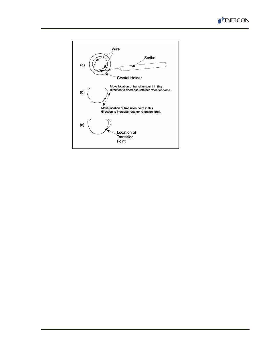
Figure 4-1 Location of the Transition Point
6
Use both pliers to form a new transition point according to
-b, thus
returning the spring to a shape similar to the solid line delineation of
-c.
7
Reinstall the spring into the groove provided in the crystal cavity.
8
Determine if the retention force is acceptable and that the wire does not impede
crystal insertion. Repeat these instructions if unacceptable retention forces
persist.
4.4 Alignment Instruction for INFICON CrystalSix Sensor
(IPN 750-446)
During shipment, units may vibrate slightly out of position. This does not mean
alignment is required. The unit will return to the centered position the first time it is
pneumatically activated.
The unit in the shipped condition has been aligned at the factory, no further
alignment is required.
NOTE: Realignment is only required if the unit has been disassembled for any
reason, such as evaporant material removal, or any electrical problem that
may occur, or if the ratchet (item #22 DWG 750-446 shown on
) is loosened, or removed. This procedure is critical and must
be carefully undertaken.
- TGF10 Tracer Gas Filler (36 pages)
- Sensistor ILS500 F Leak Detection Filler (90 pages)
- T-Guard Leak Detection Sensor (85 pages)
- T-Guard Leak Detection Sensor Interface description (40 pages)
- Sensistor ISH2000P Hydrogen Leak Detector, Panel Model (51 pages)
- Sensistor ISH2000 HySpeed Hydrogen Leak Detector (54 pages)
- LDS3000 Modular Leak Detector (52 pages)
- LDS3000 Modular Leak Detector Interface description (56 pages)
- BM1000 Bus module (14 pages)
- I/O1000 I/O module (18 pages)
- CU1000 Control unit (24 pages)
- Helium Leak Detector Modul1000 (130 pages)
- Helium Leak Detector Modul1000 Interface description (40 pages)
- UL5000 Dry Helium Leak Detector (108 pages)
- UL5000 Dry Helium Leak Detector Interface description (14 pages)
- UL1000 Fab Dry Helium Leak Detector (119 pages)
- HLD6000 Refrigerant Leak Detector (76 pages)
- HLD6000 Refrigerant Leak Detector Interface Description (40 pages)
- IO1000 I/O module (18 pages)
- Ecotec E3000 Multigas-Sniffer-Leak Detector (92 pages)
- Ecotec E3000 Multigas-Sniffer-Leak Detector Interface description (36 pages)
- Sensistor XRS9012 Hydrogen Leak Detector User Manual (28 pages)
- Sensistor XRS9012 Hydrogen Leak Detector Maintenance manual (14 pages)
- Extrima Ex-certified Hydrogen Leak Detector (62 pages)
- Sensistor ILS500 Leak Detection System (107 pages)
- Sensistor ISH2000 Hydrogen Leak Detector (58 pages)
- Sensistor ISH2000 Hydrogen Leak Detector (108 pages)
- Sensistor Sentrac Hydrogen Leak Detector (86 pages)
- Protec P3000(XL) Helium Leak Detector (132 pages)
- Pilot Plus Vacuum Gauge (2 pages)
- CO Check Carbon Monoxide Meter (2 pages)
- GAS-Mate Combustible Gas Leak Detector (12 pages)
- Whisper Ultrasonic Leak Detector (8 pages)
- Vortex AC Refrigerant Recovery Machine 115V (20 pages)
- Vortex AC Refrigerant Recovery Machine 230V (16 pages)
- Wey-TEK Refrigerant Charging Scale & Optional Charging Module (2 pages)
- Wey-TEK Refrigerant Charging Scale & Optional Charging Module (44 pages)
- D-TEK CO2 Refrigerant Leak Detector (12 pages)
- TEK-Mate Refrigerant Leak Detector (12 pages)
- Compass Refrigerant Leak Detector (12 pages)
- D-TEK Select Refrigerant Leak Detector (12 pages)
- Explorer Portable Gas Chromatograph (369 pages)
- MicroFID II Portable Flame Ionization Detector (89 pages)
- DataFID Portable Flame Ionization Detector for Landfill Emissions Monitoring (91 pages)
- Hydrostik Hydrogen Fuel Cylinder Installation (7 pages)