1 programming the relay outputs – INFICON CrystalSix Sensor User Manual
Page 27
2 - 13
IP
N 07
4-
15
5L
CrystalSix Operating Manual
2.6 CrystalSix Sensor Installation when used
with an IC/4 or IC/4 PLUS
2.6.1 Programming the Relay Outputs
1
From the program menu select Source/Sensor (F4).
2
Select Sensor board 1 or Sensor board 2.
3
Enter the edit mode. (F5)
4
Select Sensor type six (6) for the CrystalSix Sensor. This will enable the
CrystalSwitch output.
5
Select a CrystalSwitch output (Relay 1-8 or 1-16) depending upon which I/O
board is used.
6
Turn the instrument’s power “OFF”, then “ON”, to ensure that the change takes
place permanently.
2.6.2 Wiring the Relay Outputs with Relay I/O Boards
755-122-G1 or 755-122-G1/G2
1
, connect the leads of the
solenoid valve across the one side of a 24 volt supply (see listing) and one side
of a relay (1-16 whichever was programmed). Connect a jumper between the
second side of the 24 volt supply and the second side of the selected relay.
Refer to
for a typical installation utilizing relay 1 to
perform the crystal advance function for the relay I/O board.
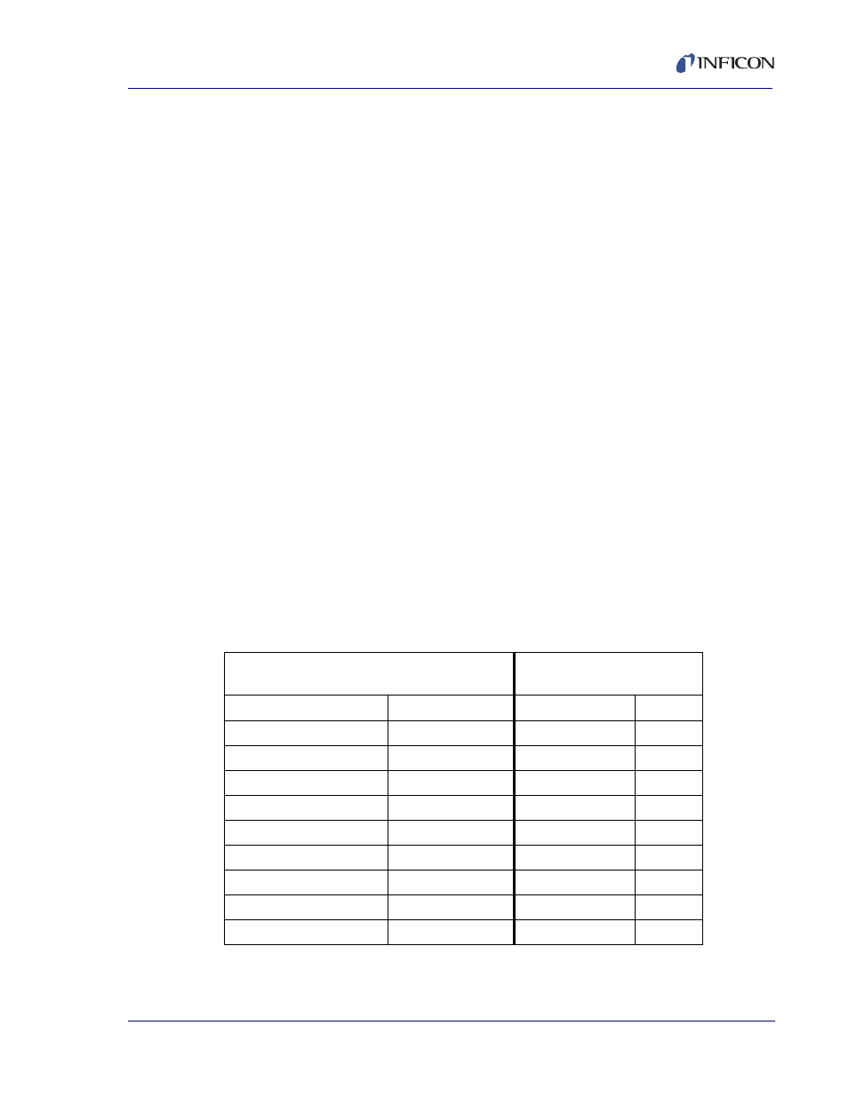
Table 2-1 Wiring Connectors
(P4)
Top Relay Connector
(P5)
Input Lines
Relay
Pins
Input
Pins
1
24, 28
1
1, 20
2
23, 27
2
2, 21
3
22, 26
3
3, 22
4
13, 19
4
4, 23
5
12, 18
5
5, 24
6
11, 17
6
6, 25
7
10, 16
7
7, 26
8
3, 7
8
8, 27