6 gas evacuation, 7 tooling disconnection, 4 optimizing the test cycle – INFICON Sensistor ILS500F Leak Detection System User Manual
Page 46: Optimizing the test cycle, 6 gas evacuation 7.3.7 tooling disconnection
Recipes
46
ninp69e1-a (1410)
7.3.6
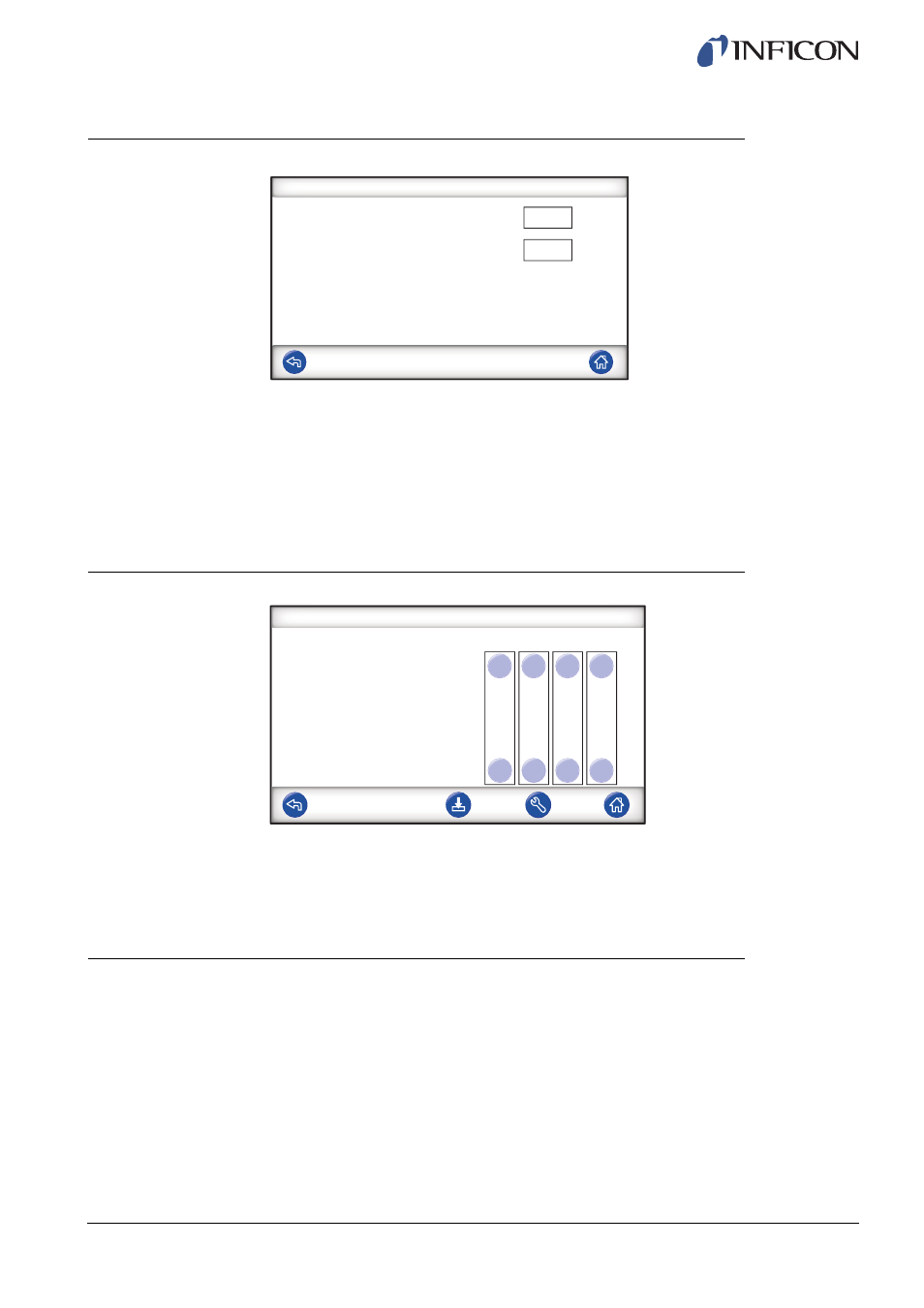
Gas Evacuation
7.3.7
Tooling Disconnection
Same function as Tooling Connection but in revers order.
For information about this step, see on page 40.
7.4
Optimizing the Test Cycle
Test Cycle can be divided in six main blocks:
1
Connection of Tested Object
2
Pre Evacuation of Residual Air
3
Filling with Tracer Gas
4
Tracer Gas Leak Test
5
Removal and Venting of Tracer Gas
6
Disconnection of Tested Object
Gas Evacuation
Gas Evacuation Setpoint
Extended Gas Evacuation
-0,30
0,0
bar
s
Gas Evacuation Setpoint
Set desired level of Gas Evacuation.
-30 kPa (-0.3 bar, -4.4 psi) creates 30% vacuum,
which is adequate for most applications.
Extended Gas Evacuation
Extends time for gas evacuation, after Gas
Evacuation Setpoint has been reached.
Disconnection Sequence
Tooling Outputs
Test
Step
Step
Step
Stand-by
1
2
3
OFF
OFF
OFF
1
2
3
4