Design, General assembly procedure – ERICO ISODC Isolated Downconductor System User Manual
Page 8
8
www.erico.com
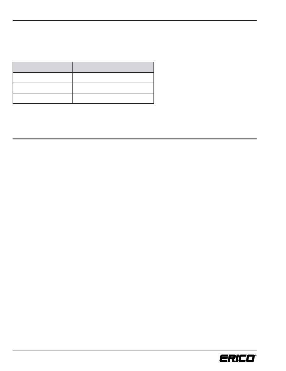
The ISODC Isolated Downconductor has an equivalent separation distance of 1000 mm of air. Therefore simplifying the equation in Table 3, Table 4
provides the maximum length for a single downconductor where the lower termination is equipotentially bonded to the structure. If it is not possible
to adhere to the distance limitations, then refer to Annex A for information on the ISODUAL dual coupling.
Class of LPS
(Lightning Protection Level)
Maximum Isolated Downconductor length
I
12.5 m
II
16.6 m
III & IV
25 m
Table 4. Maximum Isolated Downconductor length for single equipotential bonded cable.
Where the lower termination is not equipotentially bonded to the structure, such as when connected to an isolated ring system, then distance must
be measured to the nearest LPS-structural equipotential point. Contact ERICO
®
for advice.
1. DESIGN
(continued)
Follow procedures appropriate for the site. However, it is generally recommended to:
1. Check sufficient Isolated Downconductor length is available for planned route.
2. Assemble the Isolated Mast, air terminal and Isolated Downconductor together, before mounting the arrangement to
the structure.
3. Attach the mast mounting brackets to the structure.
4. Hoist and attach assembled mast/air terminal/downconductor arrangement to the structure.
5. Connect ISODC primary equipotential bond conductor to support mast.
6. Route and secure the Isolated Downconductor.
7. Cut bottom of Isolated Downconductor to final length, install lower termination and connect to grounding/lightning
protection system.
2. GENERAL ASSEMBLY PROCEDURE