Can communication – ElmoMC Multi-Axis Motion Controller-Gold Maestro User Manual
Page 25
Gold Maestro Installation Guide
Installation
MAN-GOLD-MAESTRO-IG (Ver. 1.301)
25
3.5.5.
CAN Communication
Notes for connecting the CAN communication cable:
Use 26 or 28 AWG twisted pair shielded cables. For best results, the shield should have
aluminum foil and be covered by copper braid with a drain wire (CAT5e FTP applicable).
Connect the shield to the ground of the host (PC). Usually, this connection is soldered internally
inside the connector at the PC end. You can use the drain wire to facilitate connection.
The male RJ plug must have a shield cover.
Ensure that the shield of the cable is connected to the shield of the RJ plug. The drain wire can
be used to facilitate the connection.
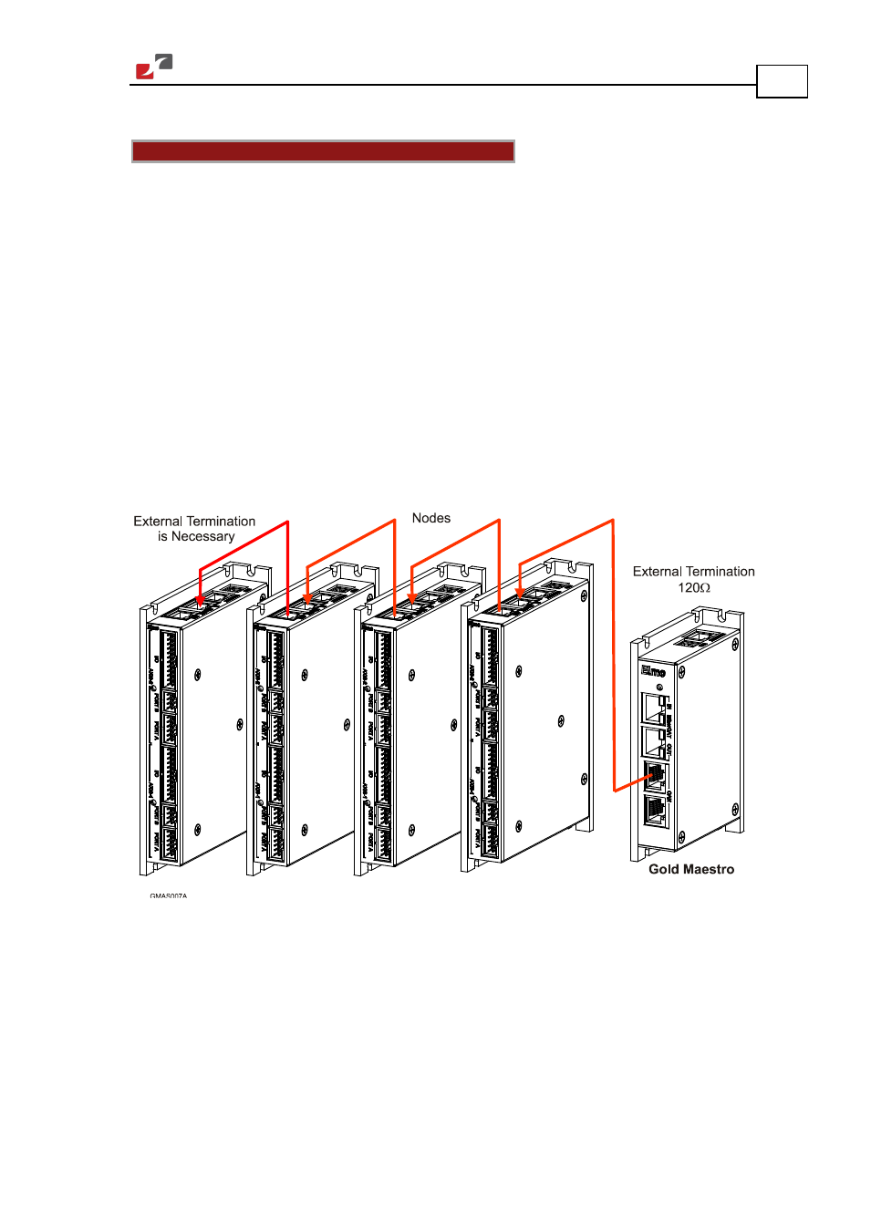
Connect a 120 Ω termination resistor to each end of the network cable.
(The Gold Maestro does not have an internal terminal.)
Termination resistors should be installed in all the unused CAN ports on the Gold Maestro.
Use the CAN termination dongle supplied as a second “device end”. Simply insert the
termination resistor into the CAN connector of the second end device on the bus. This is only
possible if there are two CAN connectors.
Figure 9: Connecting a 120 Ω Termination Resistor to Each End of the Network Cable