Connecting the cables, Wiring the gold maestro – ElmoMC Multi-Axis Motion Controller-Gold Maestro User Manual
Page 21
Gold Maestro Installation Guide
Installation
MAN-GOLD-MAESTRO-IG (Ver. 1.301)
21
3.5. Connecting the Cables
3.5.1.
Wiring the Gold Maestro
Once the Gold Maestro is mounted, you are ready to wire the device. Proper wiring, grounding
and shielding are essential for ensuring safe, immune and optimal performance of the Gold
Maestro.
Caution: Follow these instructions to ensure safe and proper wiring.
•
Use twisted pair shielded cables for communication connections. For best results, the
cable should have an aluminum foil shield covered by copper braid, and should contain
a drain wire.
The drain wire is a non-insulated wire that is in contact with parts of the cable, usually the
shield. It is used to terminate the shield and act as a grounding connection.
•
Use CAT5e cables for Ethernet and EtherCAT communication.
•
Keep all wires and cables as short as possible.
•
Ensure that in normal operating conditions, the shielded wires and drain carry no
current. The only time these conductors carry current is under abnormal conditions,
when electrical equipment has become a potential shock or fire hazard while
conducting external EMI interferences directly to ground. This is in order to prevent
them from affecting the controller. Failing to meet this requirement can result in drive,
controller or host failure.
•
After completing the wiring, carefully inspect all wires to ensure tightness, good solder
joints and general safety.
Caution: When the EtherCAT is connected, and FoE in operation, the USB
cable connection must be disconnected.
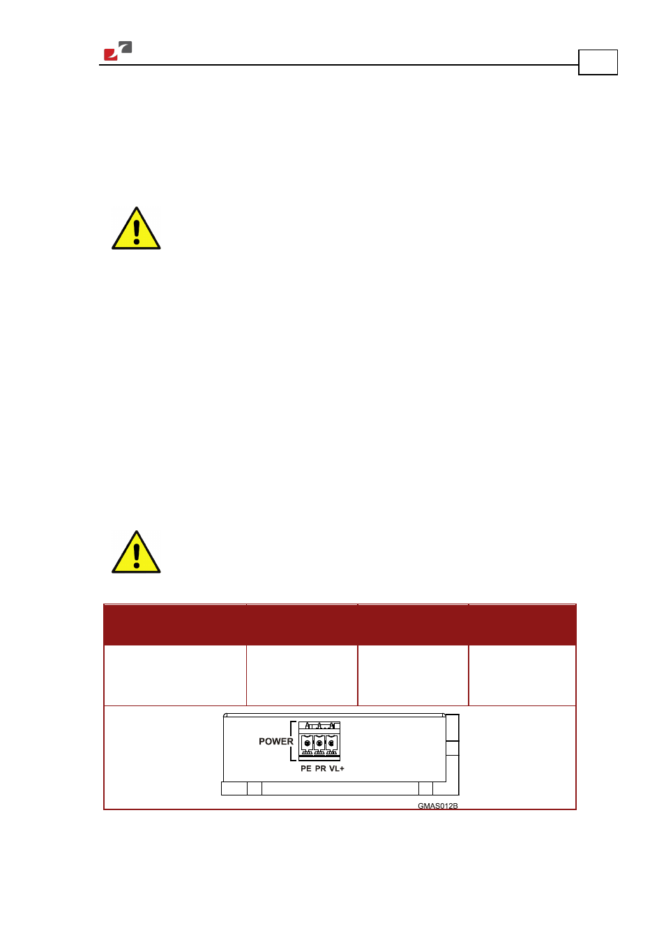
The following connectors are used for wiring the Gold Maestro:
Type
Manufacturer &
Part No.
Mating
Connector
Port
3.81 mm pitch
Header and Plug
Phoenix Header
MC 1.5/3-G-3.81
Phoenix Plug
(supplied)
MC 1.5/3-ST-3.81
Power
PE, PR, VL+
Table 8: Gold Maestro Power and Ground Connectors