Det-Tronics R8471NH34001,2,3 Single Channel Gas Controller, NH3 User Manual
Page 8
95-8529
1.1
6
Automatic Diagnostics and Fault Identification
The microprocessor based controller features self-
testing circuitry that continuously checks for problems
that could prevent proper system response. When
power is applied, the microprocessor automatically
tests memory. In the Normal operating mode, it
continuously monitors the input signal from the
sensor to ensure proper functioning. In addition, a
“watchdog” timer is maintained to ensure that the
program is running correctly. If a fault should occur:
– The Fault LED flashes.
– The digital display identifies the nature of the fault
(for 2 out of every 5 seconds) using a prioritized
alpha-numeric fault code. Refer to Table 6 for an
interpretation of the codes.
– The normally energized Fault output is de-energized.
– The current output drops to less than 1.0 ma.
An alarm condition will normally over-ride a fault
condition unless the fault condition occurred first. F10
and F2X will not over-ride an alarm. Faults that affect
the actual function of the controller (F50, F60, F70,
F9X) may impair the ability of the controller to maintain
an alarm output.
All faults automatically reset except the F9X, F20,
and F10 faults. After the fault condition has been
corrected, the fault output automatically switches
to the normal (energized) state, the dc current
output returns to normal, and the Fault LED turns
off. Clearing F9X faults requires removing operating
power from the controller for approximately one
second. Press RESET to clear an F20 or F10 fault.
Over-Range Condition
In the event of an over-range condition, the digital
display flashes as long as the over-range condition
exists. The user must exercise caution if an over-
range reading is indicated, since a dangerous
condition could exist. The hazardous area should be
checked to determine the actual level of gas present.
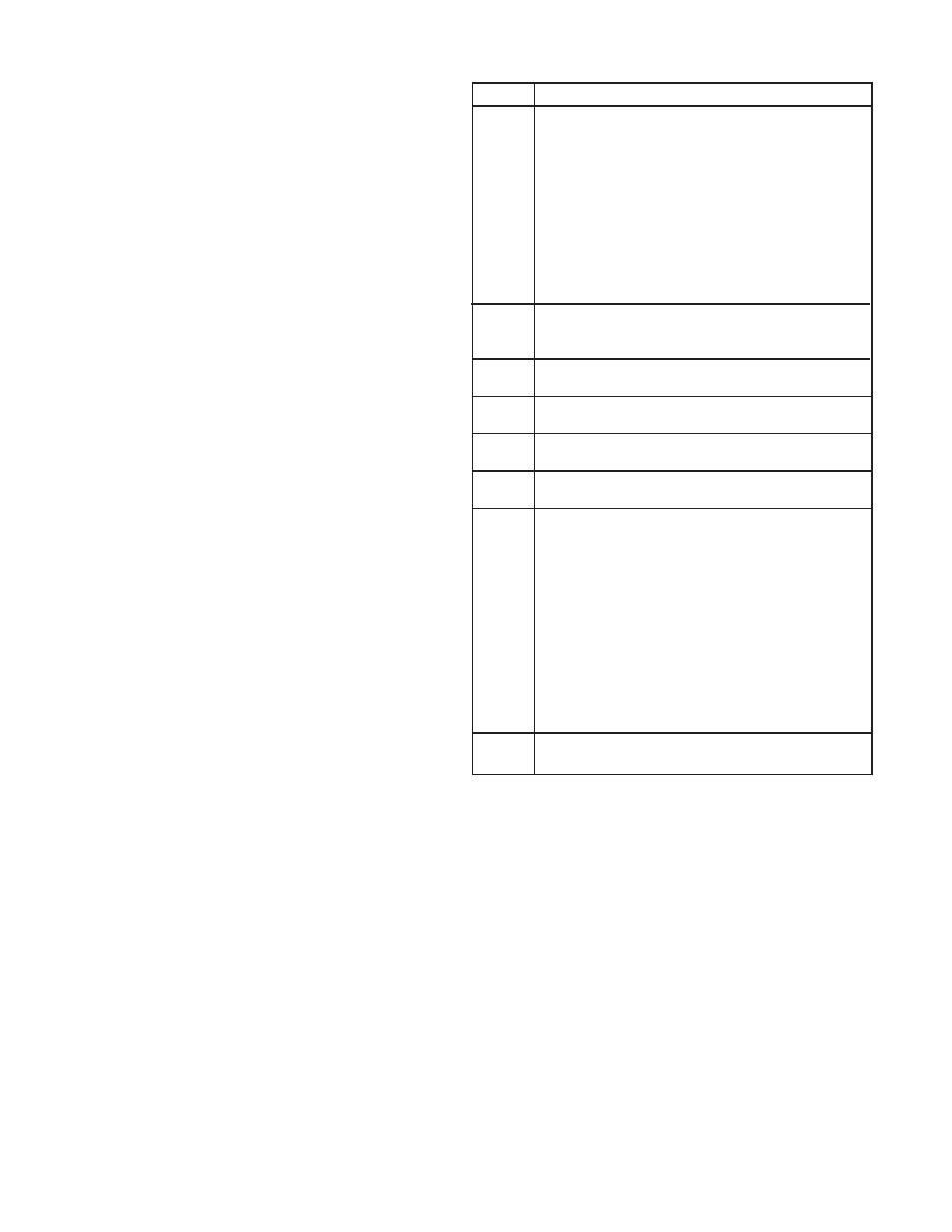
Status Condition
F9X
Initialization failure. (Subcodes are as follows.)
F91 EPROM
sumcheck
failure.
F92
System failure during startup - current too high or
too low.
F93
Watchdog timer failure.
F94 RAM
failure.
F95
Internal 5 volt power supply failure during startup.
F96
External 24 volt power supply failure during startup.
F97
Controller type invalid. Error in data from RAM.
F98
Watchdog timer reset the controller.
F70
External reset button has been activated for 15
seconds or longer. Self-clearing when button is
released.
F60
External 24 vdc power input is not in the 18 to 32
vdc range.
F50
Internal 5 volt power supply is not in the 4.75 to
5.25 volt range.
F40
Sensor fault (after startup). Input is above 35 ma
or below 2 ma.
F30
Negative zero drift. Sensor input is –9% full scale
or lower.
F2X
Calibration error. (Subcodes are as follows.)
F20
General calibration fault, or calibration aborted due
to a higher priority fault.
F21
Time ran out while waiting for the user to apply gas
to the sensor.
F22
Sensor input is too low. The sensor cannot
generate enough offset to get an accurate
calibration. Replace sensor.
F23
Sensor is too sensitive for the controller to read
100% full scale. Replace sensor.
F24
Zero gas level too high, or sensor zero input over
limit.
F10
Sensor reaching end of life. Consider replacing the
sensor within the next two calibration periods.
Table 6—System Status Codes