Det-Tronics R8471NH34001,2,3 Single Channel Gas Controller, NH3 User Manual
Page 16
95-8529
1.1
14
CONTROLLER PROGRAMMING
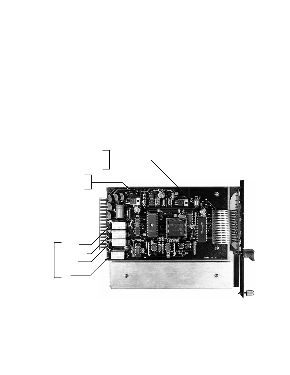
Refer to Figure 14 to determine the location of
programming jumpers and switches. Table 5 shows
the selectable options for each relay.
IMPORTANT
All jumper plugs must be installed. The
controller outputs will not function properly if a
jumper plug is missing.
Normally Open/Closed Relays
The four relays are individually programmed for either
normally open or normally closed contacts. This
is accomplished by placing a jumper plug on the
appropriate pair of pins. Each relay has a set of
three pins. For normally open operation, place the
plug on the NO and center pins. For normally closed
operation, place it on the NC and center pins. The
pin groups are identified as follows:
J2 – High Alarm
J3 – Auxiliary Alarm
J4 – Low Alarm
J5 – Fault
The controller is programmed at the factory for
normally open relay contacts.
A1392
HIGH ALARM (J2)
SW1-1
CLOSED = LATCHING
OPEN = NON-LATCHING
SW1-2
CLOSED = NORMALLY ENERGIZED
OPEN = NORMALLY DE-ENERGIZED
LOW ALARM (J4)
FAULT (J5)
AUXILLIARY ALARM (J3)
NORMALLY
OPEN/CLOSED
RELAY CONTACTS
J1
INT = NON-ISOLATED
EXT = ISOLATED
Figure 14—Programming Jumper Plugs and Switches