Det-Tronics R8471NH34001,2,3 Single Channel Gas Controller, NH3 User Manual
Page 15
13
95-8529
1.1
Base Controller –
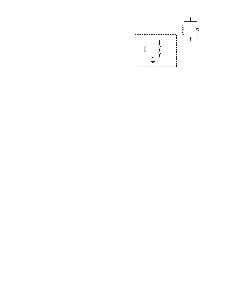
Connections to open collector
transistor outputs are made at terminals 10, 12, 14,
and 16. Terminals 9, 11, 13, and 15 are not used.
See Figure 13 for an example of a typical connection
to an open collector transistor output.
NOTE
External equipment that can generate transients
when switching (such as relays) must have
a transient suppression device (diode)
connected across the coil at the time of
installation. (Note proper polarity of the diode.)
This will safeguard the output transistors of the
controller against possible damage. Figure 13
illustrates an inductive load with a diode used for
transient suppression.
Premium Controller –
The relay outputs (terminals
9 to 16) are programmed for the desired operation
using the procedure described in the “Controller
Programming” section of this manual.
100K
OPEN COLLECTOR OUTPUT
1N4004
TYPICAL
+32 VDC MAXIMUM
B1289
Figure 13—Open Collector Output with Inductive Load and
Transient Suppression Device