Det-Tronics R8471NH34001,2,3 Single Channel Gas Controller, NH3 User Manual
Page 10
95-8529
1.1
8
SENSOR INSTALLATION AND WIRING
The maximum distance between the sensor and
controller is limited by the resistance of the connecting
wiring, which is a function of the gauge of the wire
being used. Table 7 shows the maximum wiring
distance allowed for a given wire size.
1. Determine the best mounting locations for the
sensors. Whenever practical, sensors should
be placed where they are easily accessible for
calibration.
2. The sensor junction box can be mounted to a wall
or post. The junction boxes should be electrically
connected to earth ground.
To ensure proper operation, the sensor should be
pointing down.
3. Remove the cover from the junction box.
NOTE
Do not apply power to the system with the
junction box cover removed without first verifying
that no hazardous conditions exist.
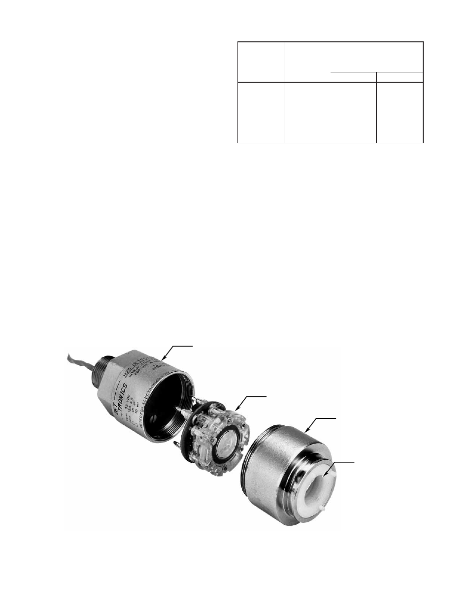
4. Remove the cap from the sensor base. See Figure
5.
5. Remove the sensor cell from its packaging.
Determine proper orientation, then
carefully
plug it
into the sensor base.
NOTE
Handle the sensor cell carefully. To avoid
possible damage, observe the proper procedures
for handling electrostatic sensitive devices. See
form 75-1005 for additional information.
6. Be sure that the O-ring is in good condition, then
place the cap back on the sensor base. Tighten
only until snug.
Do not over tighten
.
Maximum
Sensor
Wire Size
Wire Size
to Controller
(MM2) (AWG)
Distance
Feet
Meters
0.38
22
2200
670
0.56
20
3500
1050
0.96
18
5700
1750
1.3
16
9000
2800
2.1
14
14200
4300
Table 7—Maximum Wiring Distances - Sensor to Controller
B1203
SENSOR BASE
SENSOR CELL
CAP
HYDROPHOBIC FILTER
NOTE: SENSOR APPEARANCE MAY VARY
SLIGHTLY DEPENDING UPON MODEL.
Figure 5—Exploded View of Sensor