Det-Tronics R8471NH34001,2,3 Single Channel Gas Controller, NH3 User Manual
Page 12
95-8529
1.1
10
CONTROLLER WIRING
NOTE
The controller contains semiconductor devices
that are susceptible to damage by electrostatic
discharge. An electrostatic charge can build
up on the skin and discharge when an object
is touched. Therefore, use caution when
handling, taking care not to touch the terminals
or electronic components. For more information
on proper handling, refer to Service Memo form
75-1005.
Field Wiring Connector
The controller is furnished with a field wiring connector
backplate that incorporates pressure type screw
terminals for connecting the external wiring and a
circuit board edge connector for attaching to the
controller.
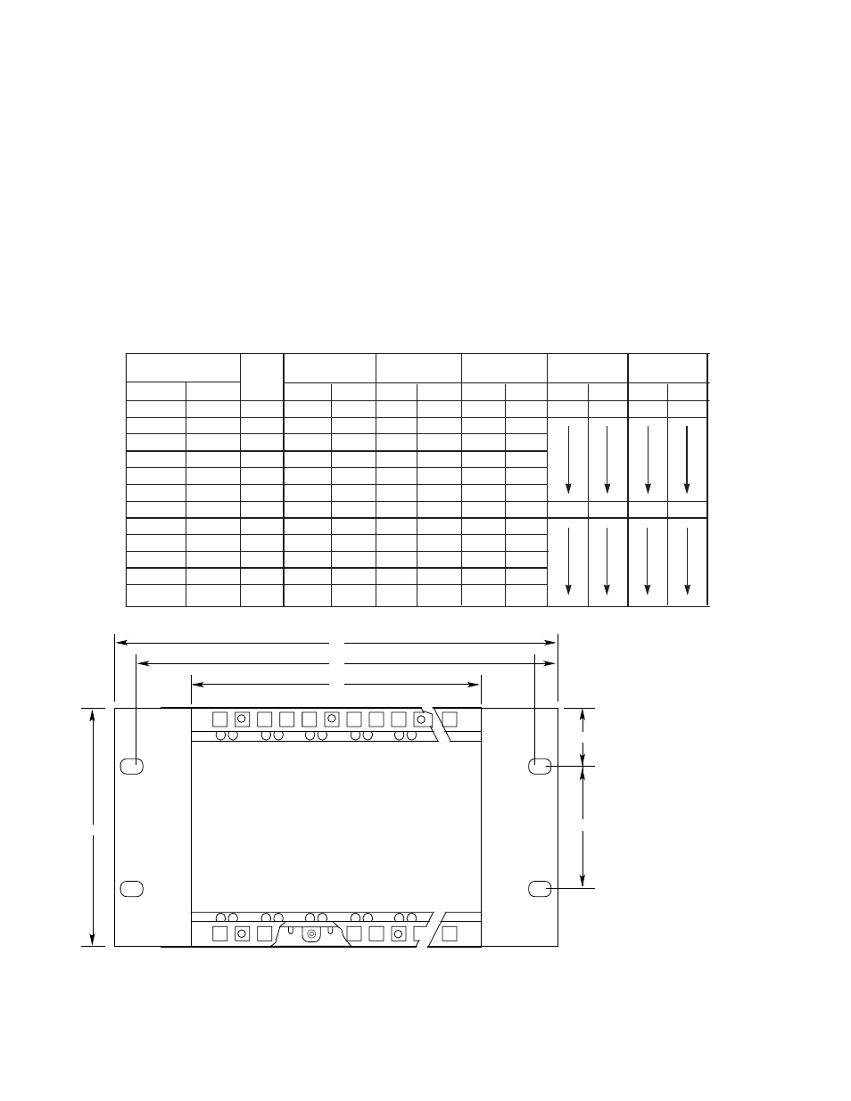
The use of a mounting rack is required for mounting
the controller. The backplate should be attached
to the back of the rack using the mounting screws
provided to allow easy removal of the controller
without disturbing the wiring. See Figures 8 and 9.
(A)
(B)
(C)
1.48 (37.59)
(D)
A1475
ALL CONTROLLER CAGES REQUIRE
A MINIMUM OF 10.12 INCHES (257.1 MM)
DEPTH CLEARANCE
(E)
CONTROLLER
POSITIONS FOR:
HT:
DIM. (A)
DIM. (B)
DIM. (C)
DIM. (D)
DIM. (E)
FIRE GAS
INCH MM
INCH MM
INCH MM
INCH MM
INCH MM
8
16
4U
19.00
482.6
18.30
464.8
17.36
440.9
4.00
101.6
6.97
177.1
6
12
4U
15.06
382.6
14.36
364.7
13.42
340.9
4
8
4U
11.13
282.6
10.43
264.9
9.49
241.1
3
6
4U
9.16
232.7
8.46
214.9
7.52
191.0
2
4
4U
7.19
182.7
6.49
164.9
5.55
141.0
1
2
4U
5.22
132.6
4.52
114.8
3.58
90.9
16
3U
19.00
482.6
18.30
464.8
17.36
440.9
2.25
57.15
5.22
132.6
12
3U
15.06
382.6
14.36
364.7
13.42
340.9
8
3U
11.13
282.6
10.43
264.9
9.49
241.1
6
3U
9.16
232.7
8.46
214.9
7.52
191.0
4
3U
7.19
182.7
6.49
164.9
5.55
141.0
2
3U
5.22
132.6
4.52
114.8
3.58
90.9
Figure 8—Dimensions of Mounting Rack