Det-Tronics R8471NH34001,2,3 Single Channel Gas Controller, NH3 User Manual
Page 13
11
95-8529
1.1
The controller is designed for installation in a non-
hazardous area.
Figure 10 shows the terminal configuration for the
controller.
Terminals 1 and 2 –
4 to 20 ma dc output.
Non-Isolated Current Output
-
If the 4 to 20 ma current loop
is to be non-isolated, wire
the current loop as shown in
Figure 11. Note that terminal 2
is not used with a non-isolated
current loop. Program the
controller for a non-isolated
current loop as described in
the “Controller Programming”
section of this manual.
Isolated Current Output -
If
an isolated current loop is
desired, wire the current loop
as shown in Figure 12 and
program the controller for
an isolated current loop as
described in the “Controller
Programming” section of this
manual. Note that this wiring
scheme requires an external
power source for the isolated
current output.
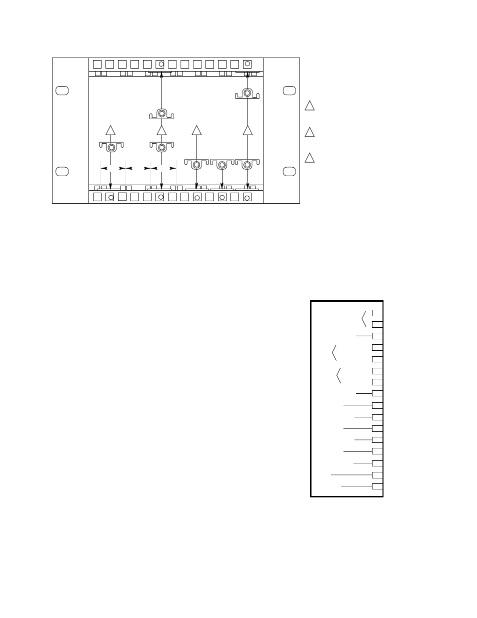
1
A1476
FIRE CONTROLLERS ARE APPROX. TWO INCHES
WIDE AND REQUIRE TWO GUIDE RAILS FOR
INSERTION. PLACE THE RETAINING CLIP BETWEEN
RAILS TO FORM SETS, LEAVE A GAP BETWEEN SETS.
SET
SET
GAP
1
2
3
2
THE Q4004 CONTROLLER CAGE HAS BEEN MODIFIED
TO ACCOMMODATE EITHER FIRE OR GAS CONTROLLERS
OR ANY COMBINATION OF THE TWO.
BY FOLLOWING THE INSTRUCTIONS BELOW, THE CAGE
CAN BE SET UP TO ANY CONFIGURATION.
2
TO INSERT A BLANK PANEL, PLACE A CLIP IN
THE TOP BRACKET IN LINE WITH THE CLIP IN THE
BOTTOM BRACKET.
3
GAS CONTROLLERS ARE APPROX. ONE INCH WIDE
AND REQUIRE ONE RAIL FOR INSERTION. PLACE CLIPS
IN LINE WITH GUIDE RAILS, CAGES WILL ACCEPT AS
MANY GAS CONTROLLERS AS RAILS PROVIDED.
Figure 9—Clip Positioning for Mounting Racks
CURRENT OUTPUT
CHASSIS GROUND
POWER
SENSOR
EXTERNAL RESET
HIGH ALARM
HIGH ALARM / OC
AUX. ALARM
AUX. ALARM / OC
LOW ALARM
LOW ALARM / OC
FAULT
FAULT / OC
1
3
4
5
6
7
8
9
10
11
12
13
14
15
16
–
+
+
–
+
–
18 TO 32
VDC
POWER
SIGNAL
2
OC = OPEN COLLECTOR OUTPUT
(BASE MODEL ONLY)
B1390
Figure 10—Controller Terminal Configuration