Det-Tronics R8471NH34001,2,3 Single Channel Gas Controller, NH3 User Manual
Page 11
9
95-8529
1.1
7. Attach the sensor to the junction box. Do
not
over
tighten.
NOTE
Coat the sensor threads with an appropriate
grease to ease installation. Also lubricate the
junction box cover threads. The recommended
lubricant is a silicone free polyalphaolefin grease,
available from Detector Electronics. If catalytic
combustible sensors are present, do not use a
silicone based grease.
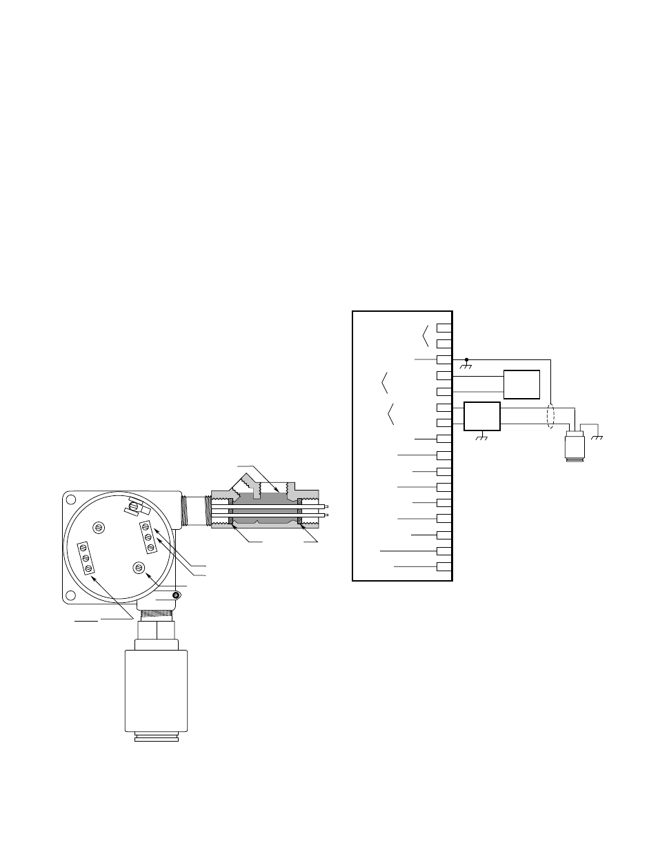
8. Connect the sensor wires to the sensor terminal
block inside the junction box. (See Figure 6.)
Connect the controller wiring to the controller
terminal block inside the junction box.
Connect the shield to earth ground at the controller
end only. Under normal conditions, the other end
of the shield should not be connected at the sensor
junction box.
The wiring code is:
Red
lead =
“+/power”
Black
lead
=
“-/signal”
Green lead = Chassis (earth) ground
In order to maintain the intrinsically safe rating of the
C7067E chlorine sensor, it must be wired through an
approved I.S. barrier. See Figure 7.
NOTE
When an I.S. barrier is used, the input voltage
(measured at the controller) must be between 23
and 26.6 vdc to ensure proper operation of the
sensor and barrier.
9. Check the sensor wiring to ensure proper
connections, then pour the conduit seals and allow
them to dry (if conduit is being used).
10. Place the cover back on the junction box.
SENSOR
GROUND
BLK (–) TO TERMINAL 7
RED (+) TO TERMINAL 6
WIRING TO CONTROLLER
GROUND JUNCTION BOX
ACCORDING TO LOCAL CODES
B1528
RED
BLK
GRN
=
=
=
+
–
GROUND
FIBER FILLER
SEALING COMPOUIND
Figure 6—Sensor Wiring
CURRENT OUTPUT
CHASSIS GROUND
POWER
SENSOR
EXTERNAL RESET
HIGH ALARM
HIGH ALARM / OC
AUX. ALARM
AUX. ALARM / OC
LOW ALARM
LOW ALARM / OC
FAULT
FAULT / OC
1
3
4
5
6
7
8
9
10
11
12
13
14
15
16
–
+
+
–
+
–
18 TO 32
VDC
POWER
SIGNAL
24
VDC
*
+
–
C7067E
SENSOR
2
A1704
R8471D CONTROLLER
BLK
RED
GREEN
+
–
MTL 787S
OR
MTL 788
OC = OPEN COLLECTOR OUTPUT
(BASE MODEL ONLY)
*
WHEN USING AN I. S. BARRIER,
INPUT VOLTAGE MUST BE 23 TO 26.6 VDC.
Figure 7—R8471D Controller and C7067E Sensor
Used with I.S. Barrier