Installation, Calibration – Det-Tronics UD10 FlexVu Explosion-Proof Universal Display Unit User Manual
Page 66
4.2
95-8661
M-3
instAllAtion
wIRINg REQUIREmENTS
The simplest installation involves installing the sensor
into one of the UD10 openings and connecting the
wiring directly to the CGS interface board.
Sensor Separation
If the installation requires separation of the CGS sensor
and the UD10 Display, the sensor can be connected to
a model STB1 sensor termination box, and the CGS/
STB combination wired to the UD10.
In this case, shielded cable is recommended to help
protect against interference caused by extraneous
electrical “noise.”
In applications where the cable is installed in conduit,
the conduit should not be used for wiring to other
electrical equipment whenever possible. If other
equipment power wiring is run in the same conduit, the
cabling must be shielded.
The maximum allowable distance between the
CGS sensor and UD10 Display Unit is 500 feet, with
connecting cable 16 AWG minimum.
INSTAllATION AND wIRINg pROCEDURE
1. Determine the best mounting locations for the
detectors.
2. Install the CGS sensor within the proper opening in
the UD10 or STB junction box. Mount the device
with the sensor oriented vertically and the opening
pointing down. All junction boxes should be
electrically connected to earth ground.
3. Terminate all wiring at the proper terminals. Refer to
the appropriate illustration for details.
4. Double check that all wiring is the proper size and
type and has been installed correctly. Check for
correct operating voltage at the device.
noTe
Do not apply power to the system with the junction
box cover removed unless the area has been
de-classified.
5. Proceed with startup and calibration.
cAlibrAtion
To initiate calibration of the CGS sensor from the UD10
Display:
1. Using the magnet to activate the switches on the
UD10 display, navigate to the “Calibrate” menu.
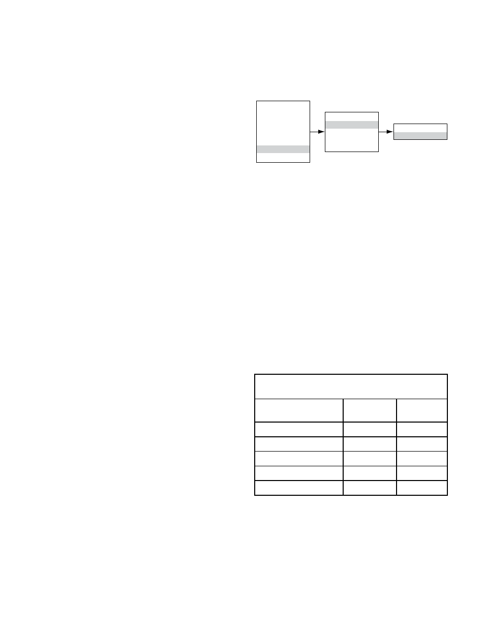
Main Menu
Process Vars
Display Status
Device Status
Display Setup
Device Setup
Device Cal
Display Test
Device Cal
Calibration
Cal Gas
Cal Gas Concentration
K Factor
Calibration
Execute
2. Activate “Execute” (Enter/Select) to start calibration.
3. The UD10 will display “Waiting for Zero” on the main
display screen as it performs zero calibration.
4. When zero calibration is complete, the UD10 will
display “Waiting for Gas” on the screen.
5. Apply calibration gas to the sensor.
6. The UD10 will display “Waiting for Span” on the
screen while the span calibration is being performed.
7. When the UD10 shows “Remove Cal Gas” on the
screen, remove the calibration gas from the sensor.
8. The UD10 automatically exits the Calibrate mode and
returns to normal operating mode upon completion
of a successful calibration.
UD10 mA Output During Calibration
(UD10 with CgS)
UD10 Display Reading
Standard
mode
Replicate
mode
Apply Zero Gas
3.8
2.2
Waiting for Gas
3.8
3.8
Waiting for Span
3.8
3.8
Remove Cal Gas
3.8
3.8
back to normal
4.0
4.0