Det-Tronics UD10 FlexVu Explosion-Proof Universal Display Unit User Manual
Page 10
8
95-8661
4.2
wIRINg pROCEDURE
noTe
The following section shows the output of the
UD10 wired to a generic 4-20 mA signal receiver
in various configurations. Since the UD10 can be
used with a variety of different detection devices,
information that is specific to each detector model
(wiring, calibration, HART menus, etc.) is covered
in an Appendix that is dedicated to that device.
Refer to the appropriate Appendix at the back of
this manual for specific information when wiring
the detection system. For information on devices
not covered in an Appendix, refer to the manual
provided by the device’s manufacturer.
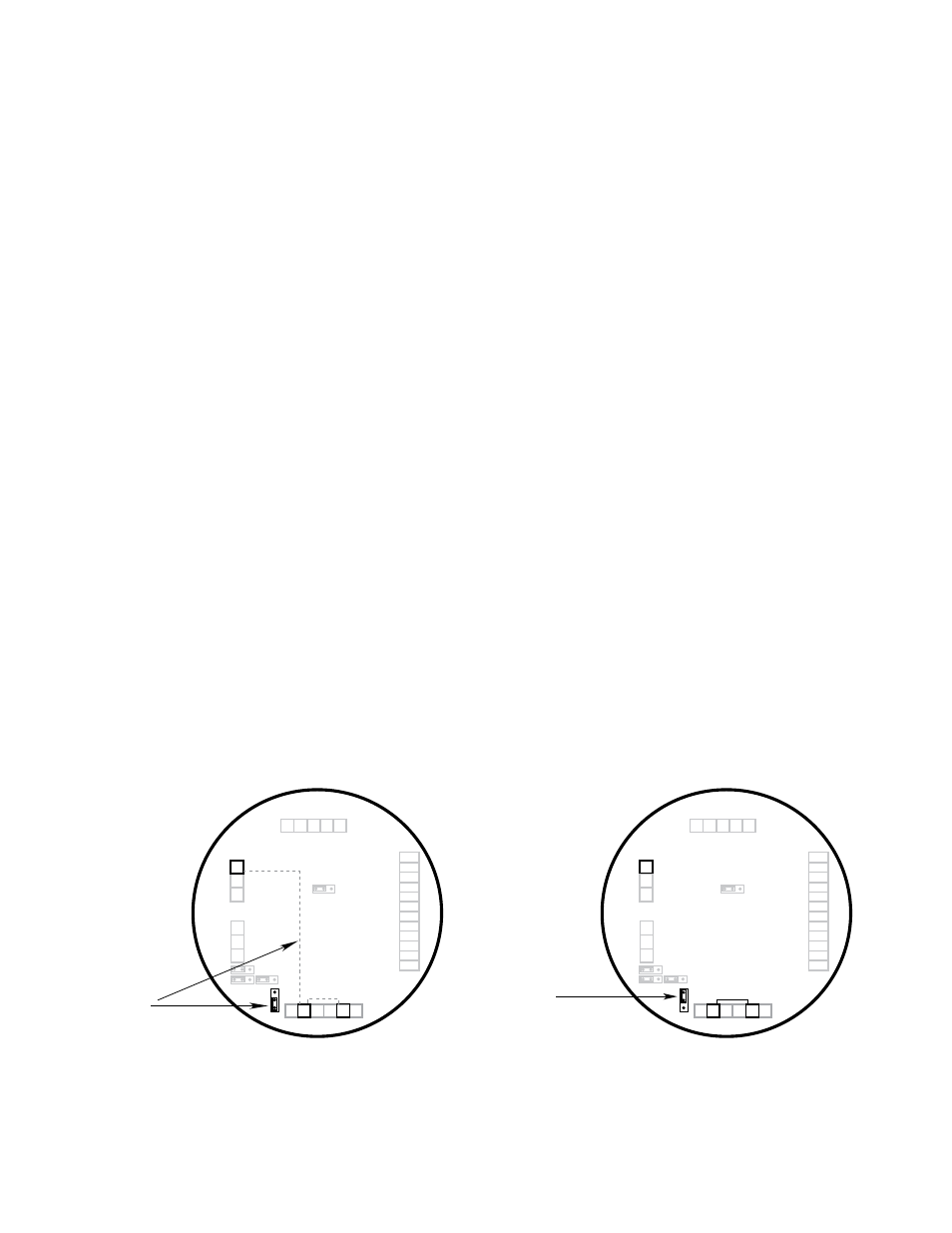
Figure 4 shows jumper plug P12 positioned to power the
4-20 mA loop from the main power source (non-isolated
output).
Figure 5 shows jumper plug P12 positioned for powering
the 4-20 mA loop from an external wire/jumper of from
a separate power source (isolated output).
Figure 6 shows the correct jumper positions and J2
terminal identification for using Foundation Fieldbus
communication.
Figure 7 shows the correct jumper positions and
J2 terminal identification for using MODBUS
communication.
Refer to Figure 8 for an illustration of the UD10 wiring
terminal board (see Figure 6 for Foundation Fieldbus
connections).
Figure 9 shows a UD10 Wired to a PLC using 3-Wire
Shielded Cable with a 4-20 mA Non-Isolated Sourcing
Output.
Figure 10 shows a UD10 Wired to a PLC using 4-Wire
Shielded Cable with a 4-20 mA Non-Isolated Sourcing
Output.
Figure 11 shows a UD10 Wired to a PLC with a 4-20 mA
Isolated Sourcing Output.
gREASE/lUBRICATION
To ease installation and future removal, ensure that all
junction box covers and sensor threads are properly
lubricated. If the need arises for additional lubrication, use
either Lubriplate grease (see Ordering Information for part
number) or Teflon tape. Avoid the use of silicone grease.
Figure 4—Position of Jumper P12 for
non-isolated 4-20 mA loop output
Sensor Connector
Power Supply Connector
Output
Loop
Connector
Fieldbus
Connector
R
ela
y Connect
or
P1
J2
J3
J4
P2
4-20 mA +
4-20 mA –
SHIELD
+
–
HIGH ALARM COM
HIGH ALARM NC
HIGH ALARM NO
AUX ALARM COM
AUX ALARM NC
AUX ALARM NO
LOW ALARM COM
LOW ALARM NC
LOW ALARM NO
FAULT COM
FAULT NC
FAULT NO
24 VDC
–
24 VDC
+
SHIELD
24 VDC
–
24 VDC
+
SHIELD
SHIELD
C
ALIBR
A
TE
24 VDC
–
4-20 mA
24 VDC
+
P1-3
P1-2
P1-1
J2-3
J2-2
J2-1
J4-1
J4-2
J4-3
J4-4
J4-5
J4-6
J4-7
J4-8
J4-9
J4-10
J4-11
J4-12
J3-1
J3-2
J3-3
J3-4
J3-5
P2-6
P2-5
P2-4
P2-3
P2-2
P2-1
P5
P9
P7
P12
P3
B2525
WHEN P12 IS
IN THIS POSITION,
P1-3 IS INTERNALLY
CONNECTED TO
P2-2 AND P2-5
Figure 5—Position of Jumper P12 for
isolated 4-20 mA loop output
Sensor Connector
Power Supply Connector
Output
Loop
Connector
Fieldbus
Connector
R
ela
y Connect
or
P1
J2
J3
J4
P2
4-20 mA +
4-20 mA –
SHIELD
+
–
HIGH ALARM COM
HIGH ALARM NC
HIGH ALARM NO
AUX ALARM COM
AUX ALARM NC
AUX ALARM NO
LOW ALARM COM
LOW ALARM NC
LOW ALARM NO
FAULT COM
FAULT NC
FAULT NO
24 VDC
–
24 VDC
+
SHIELD
24 VDC
–
24 VDC
+
SHIELD
SHIELD
C
ALIBR
A
TE
24 VDC
–
4-20 mA
24 VDC
+
P1-3
P1-2
P1-1
J2-3
J2-2
J2-1
J4-1
J4-2
J4-3
J4-4
J4-5
J4-6
J4-7
J4-8
J4-9
J4-10
J4-11
J4-12
J3-1
J3-2
J3-3
J3-4
J3-5
P2-6
P2-5
P2-4
P2-3
P2-2
P2-1
P5
P9
P7
P12
P3
B2526
WHEN P12 IS IN
THIS POSITION, A
SEPARATE POWER
SOURCE IS REQUIRED
TO POWER THE
4-20 MA LOOP