Det-Tronics UD10 FlexVu Explosion-Proof Universal Display Unit User Manual
Page 16
14
95-8661
4.2
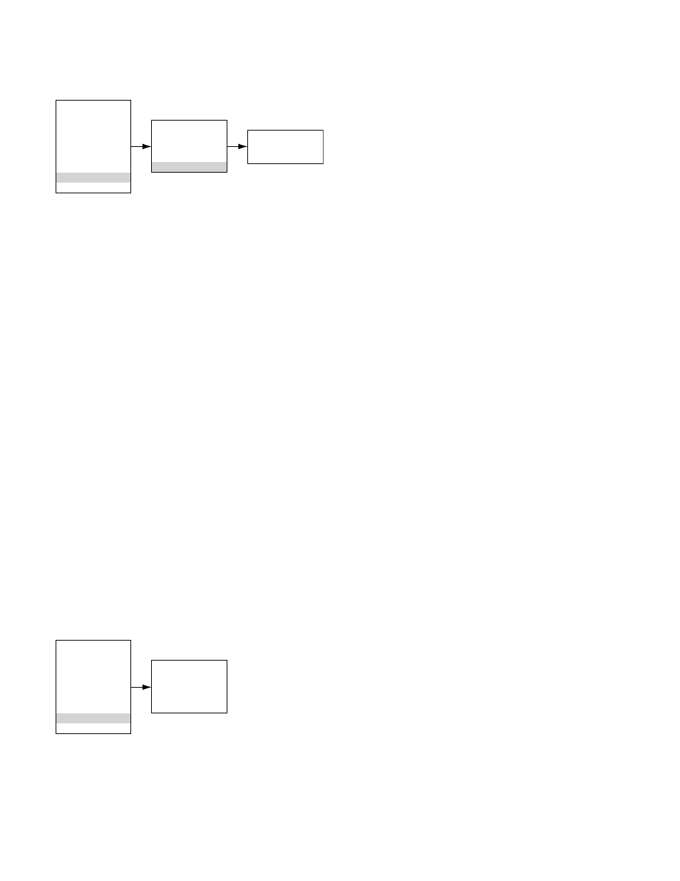
UD10 Output Trim
To calibrate the UD10 output loop, navigate down the
menu to Display Test > D/A Trim.
Main Menu
Process Vars
Display Status
Device Status
Display Setup
Device Setup
Device Cal
Display Test
Device Test
Display Test
Self Test
Response Test
Loop Test
D/A Trim
D/A Trim
Zero Trim
Gain Trim
Select Zero Trim. When this screen is entered, a warning
message is presented. Select ENTER to continue.
When the message “Connect Reference Meter” is
presented, install the current meter on the UD10 mA
output. Select ENTER to continue. When the message
“Set Output Current to 4mA?” is presented, select
ENTER to begin the Zero Trim function. The UD10
will now set its 4 mA output value. If the measured
value on the current meter is not 4.00 mA, enter the
measured value into the UD10 using the Previous and
Next switches. The UD10 calculates and corrects for
the difference between the actual and entered values.
When the current meter value is at the desired 4.00 mA,
select ENTER to accept the new zero trim value.
Select Gain Trim. Follow the same procedure for gain/
span calibration.
OpTIONAl SySTEm TESTS
The following tests are available for verifying proper
operation of various functions of the gas detection
system:
– The Self Test, Response Test, and Loop Test are
accessed from the “Display Test” screen. (A “Device
Test” screen is available for performing the same
tests on HART enabled detectors.)
– The Proof Test is performed by applying test gas
to the sensor. It is not accessed from the “Display
Test” screen and does not inhibit the outputs.
Main Menu
Process Vars
Display Status
Device Status
Display Setup
Device Setup
Device Cal
Display Test
Device Test
Display Test
Self Test
Response Test
Loop Test
D/A Trim
Self-Test
This test commands the UD10 to perform a fully
automatic internal test. At the completion of the test,
the UD10 will indicate a pass or fail.
Response Test
This test inhibits the UD10’s outputs, thereby providing a
means of testing the system by applying gas to the detector
without activating any alarms or affecting the output.
noTe
If the Response Test is not terminated by the
operator, the test will automatically time out after
ten minutes and the UD10 will return to normal
operation.
loop Test
This test temporarily forces the UD10’s 4-20 mA output
to a specific level. This is an easy way to test the output
signal of the UD10 for accuracy, to verify the capabilities
of the system, and to verify the input signal of a receiver.
To perform this test, connect a current meter to the
output loop. Navigate to Display Test and select Loop
Test, then follow the prompts on the UD10 Screen.
noTe
If the Loop Test is not terminated by the operator,
the test will automatically time out after one minute
and the UD10 will return to normal operation.
proof Test
A Proof Test (bump test) can be performed at any time
to verify proper operation and calibration of the system.
Since this test does not inhibit the UD10’s outputs, secure
any output devices prior to performing the test to prevent
unwanted actuation.
HISTORy
There are two separate histories, one for the display
and one for the detector (if available). Both will state
the number of hours that the unit has been operating,
and the highest and lowest recorded temperature (with
time and date stamp).