Appendix f, Wiring, Menu structure – Det-Tronics UD10 FlexVu Explosion-Proof Universal Display Unit User Manual
Page 31
F-1
95-8661
4.2
AppenDix f
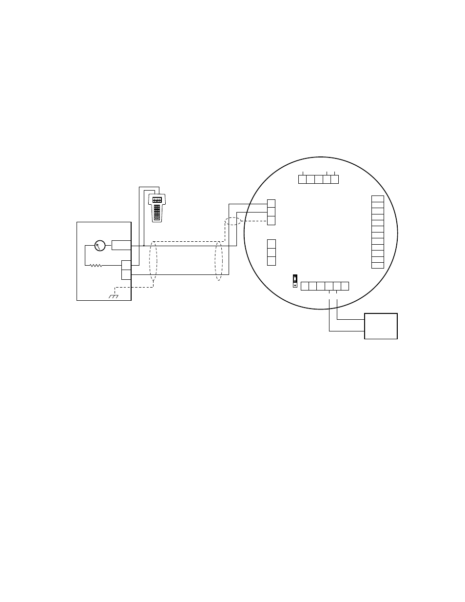
USINg A HANDHElD HART DEvICE CONNECTED TO THE UD10’S 4-20 mA OUTpUT
(UD10 wITH ANy DETECTOR)
noTe
Refer to the front of this manual for complete information regarding installation, wiring and startup of the UD10.
WirinG
Important
To ensure proper operation of the HART communication system, a power supply with low noise and ripple must
be used. If noise or ripple on the main power source could interfere with the HART function, an isolated power
source is recommended. For additional information, refer to “Power Supply Requirements” in the Wiring section
of this manual.
menu structure
Refer to the following menu tree when using a HART handheld communicator, connected to the UD10’s 4-20 mA
output.
menu HeLp
Status menus only allow the user to view the data.
The Setup menus allow the user to both view and edit the data.
Sensor Connector
Power Supply Connector
Output Loop
Connector
MODBUS
Connector
R
ela
y Connect
or
P1
J2
J3
J4
P2
4-20 mA +
4-20 mA –
SHIELD
COM
RS485 A
RS485 B
HIGH ALARM COM
HIGH ALARM NC
HIGH ALARM NO
AUX ALARM COM
AUX ALARM NC
AUX ALARM NO
LOW ALARM COM
LOW ALARM NC
LOW ALARM NO
FAULT COM
FAULT NC
FAULT NO
24 VDC
–
24 VDC
+
SHIELD
24 VDC
–
24 VDC
+
SHIELD
SHIELD
C
ALIBR
A
TE
24 VDC
–
4-20 mA
24 VDC
+
P1-3
P1-2
P1-1
J2-3
J2-2
J2-1
J4-1
J4-2
J4-3
J4-4
J4-5
J4-6
J4-7
J4-8
J4-9
J4-10
J4-11
J4-12
J3-1
J3-2
J3-3
J3-4
J3-5
P2-6
P2-5
P2-4
P2-3
P2-2
P2-1
UD10
DISPLAY UNIT
D2441
24 VDC
24 VDC
INPUT
4-20 mA
PLC 4-20 mA INPUT CARD
–
–
+
+
250-600
OHMS
Notes: Resistor may be external if voltage input card is used.
Sinking resistance at PLC must be 250-600 ohms
for HART communication.
P12
HART Handheld Communicator Connected to the UD10’s 4-20 mA output