Det-Tronics UD10 FlexVu Explosion-Proof Universal Display Unit User Manual
Page 6
4
95-8661
4.2
RElAyS
The display unit has 4 output relays — high alarm, low
alarm, auxiliary alarm, and fault. The relays have form
C (SPDT) contacts. Low, auxiliary and high alarm relay
contacts are selectable for latching or non-latching
operation, as well as normally energized or normally
de-energized (default) coils. During normal operation,
the fault relay is energized.
Important
Direct connection of 120/240 VAC to the
relay terminals inside the UD10 enclosure
is not allowed, since switching relay contacts
can induce electrical noise into the electronic
circuitry, possibly resulting in a false alarm or other
system malfunction. If the application requires
that AC powered equipment be controlled by the
transmitter, the use of externally located relays is
recommended.
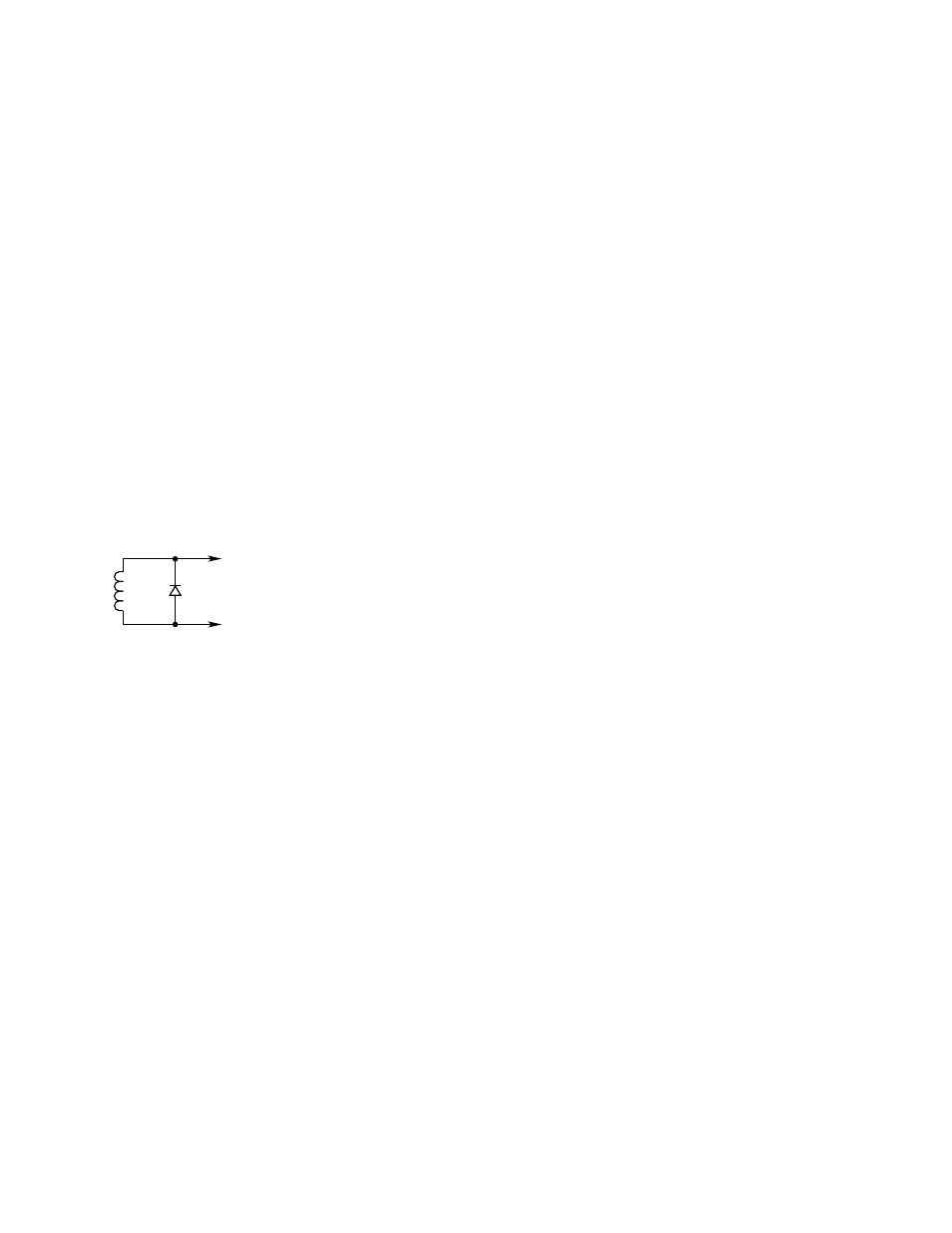
External relays, solenoids, motors, or other devices
that can cause inductive transients should be transient
suppressed. Place a diode across the coil for DC
devices. See Figure 2.
Figure 2—Transient Suppression for inductive loads
RELAY
SOLENOIDS
MOTORS
INDUCTION DEVICES
1N4004
TYPICAL
B0179
POSITIVE
NEGATIVE
MOV
HOT
NEUTRAL
120 VOLT – V13OLA10A
220/240 VOLT – V275LA20A
GE
TYPICAL
{ }
+
–
DCV LOADS
A0179
4-20 mA OUTpUT mODES
The UD10 offers two operating modes for its 4-20 mA
output circuit.
noTe
A minimum output of 1 mA is required for proper
HART communication.
In the Standard (default) Mode, the linear 4-20 mA
output corresponds to 0-100% full scale gas detected at
the sensor, with 3.8 mA indicating calibrate mode, and
3.6 mA or lower indicating a fault condition. This mode
ensures that the current level is always high enough to
support HART communication and must be selected
when using HART communication for fault diagnostics.
In Replicate Mode, the output of the UD10 matches
the output of the connected detector (except for loop
test/trim, response test, calibration, or if the UD10
has an internal fault). This mode can be used with
detectors such as PIR9400 or PIRECL where multiple
current levels below 4 mA are used for fault diagnostic
purposes.
UD10 with model pIRECl
PIRECL supports two fault modes: PIR9400 and Eclipse
mode. PIR9400 fault mode uses fault codes below 1
mA, while Eclipse mode uses no levels below 1 mA. In
the Standard (default) mode, the UD10 programs the
PIRECL for Eclipse fault mode to ensure proper HART
communication in the event of a fault. In the Replicate
mode, the UD10 programs the PIRECL for PIR9400
fault mode.
mODBUS / FIElDBUS COmpATIBIlITy
The UD10 supports RS485 Modbus RTU communi-
cation. See Addendum number 95-8639 for details. A
model with Modbus RS485 or
foundation
™
Fieldbus
communication (field selectable via jumpers) is also
available.
DEvICE ENClOSURE
The UD10 housing is a 5 port aluminum or stainless steel
explosion-proof junction box with a clear viewing window.
DEvICE DISplAy
The UD10 is provided with a 160 x 100 dot matrix backlit
LCD display. See Figure 1.
During normal operation, the LCD continuously
displays the detected gas level, gas type, and units
of measurement. The real time clock can also be
displayed if desired.
The display shows the following alarm information:
• High gas alarm
• Low gas alarm
• Aux alarm
The display indicates the following fault information:
• Device fault
• Display fault
The UD10 has smart capabilities to allow easy access
to the following information:
• Detector information
• Measurement range
• Alarm setpoints
• Alarm and event logs
For detailed HART menu structure, refer to the appropriate
Appendix.