Corrective weight placement – COATS 1100 Series Balancer User Manual
Page 19
Important: Always read and follow instructions.
• 15
Behind Spoke Mode (1150-2D only)
“Splitting” the T2 Tape corrective weight amount is
used to hide the adhesive weight behind two rim
spokes.
1.
When the unbalance is displayed, rotate wheel
until Inboard center bar blinks. Attach Inboard corrective
weight at top-dead-center.
2.
Next, rotate wheel until the outboard center bar
blinks.
3.
Select the Behind Spoke mode option. “SP1” will
display in the static display window.
4.
Rotate the wheel toward front until the first spoke
is at top-dead-center.; press Spoke and 1 illuminates.
“SP2” will display in the static display window.
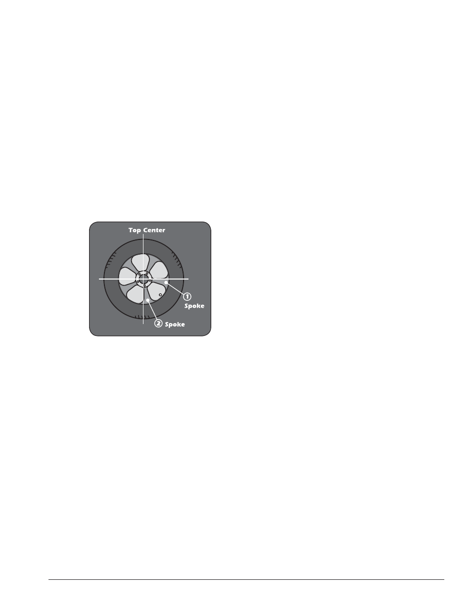
5.
Rotate the wheel toward rear until the second
spoke is at top-dead-center; press Spoke and 2 illu-
minates. Now at the Spoke 2 location, the Outboard
center bar stops blinking.
Figure 22 - Spoke 1 and Spoke 2 Locations On Either Side Of
Original Outboard Weight Location
6.
Attach the Spoke 2 Outboard corrective weight at
top-dead-center behind spoke 2.
7.
Next, rotate the wheel toward the Spoke 1 location
until the outboard center bar is blinking.
8.
Attach the Spoke 1 Outboard corrective weight at
top-dead-center behind spoke 1.
9.
Respin tire/wheel to check balance.
Corrective Weight Placement
After the wheel spins and out of balances are mea-
sured and displayed, the corrective weight amount
appears on the weight display window for Inboard and
Outboard weight locations. Bars appear on either side
of the wheel cross-section diagram to aid in positioning
the wheel for corrective weight at the application point.
After a measurement cycle, rotate wheel until the
center weight position bar blinks, indicating the cor-
rect weight placement position is at top-dead-center.
If the out-of-balance is less than the chosen threshold
value, 000 appears instead of an out-of-balance value
to indicate that, on that particular side, the wheel is in
tolerance.