COATS 1100 Series Balancer User Manual
Page 11
Important: Always read and follow instructions.
• 7
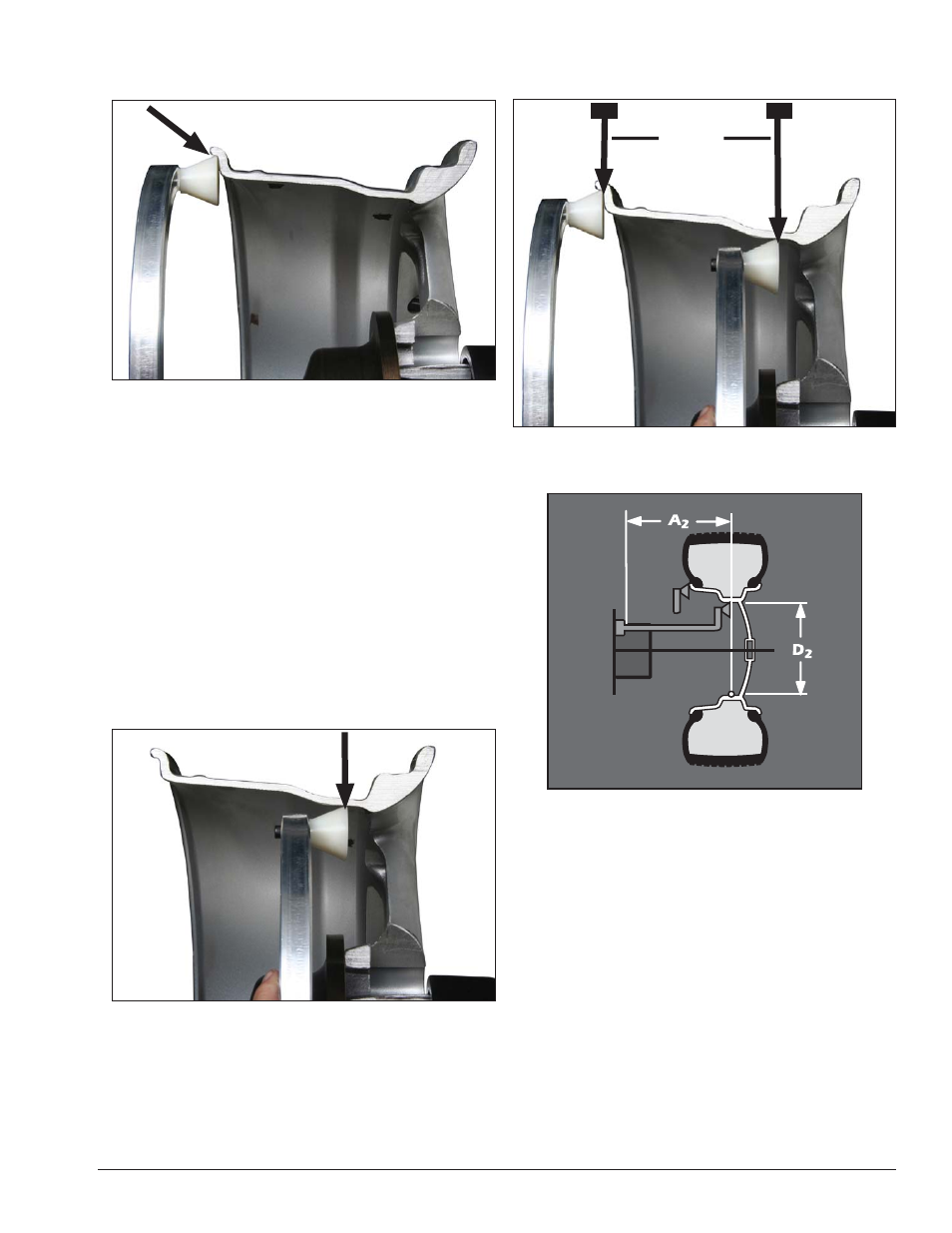
Be sure to place the offset arm on the wheel flange at
the clip-on weight location as shown, figure 8.
Figure 8 - Clip-on Weight Location Viewed on a Cut-Away Rim
for Clarification
Note: Use the offset arm to automatically measure
the A & D dimension for all balancing modes.
Note: Refer to page 13 to measure the A dimension
manually using the offset arm.
Note: The T2 Tape Direct™ Select Weight position is
the only mode that requires the A2 & D2 dimension
measurements.
If the T2 Tape (hidden Tape-A-Weight
®
) location is
selected, use the offset arm to enter A2 & D2 measure-
ments, automatically. After the A & D measurement is
entered, move the arm from the clip-on weight location
to the inner area of the wheel; up against the rim at the
Outboard weight placement location (see figures 9 &
10). Wait for the BEEP.
Figure 9 - Hidden Weight Location Viewed on a Cut-Away Rim
for Clarification
Important: The A2 measurement must be at least 2
inches greater than the A1 measurement.
Figure 10 - T2 Tape (Hidden Tape-A-Weight
®
) Keep At Least
2-inches Between A1 and A2 Measurement
Figure 11 - T2 Tape (Hidden Tape-A-Weight
®
) Data Entry Dia-
gram
At least
2-inch
minimum
difference
A1
A2