Direct drive, Caution, Optional combi adaptor – COATS 1001 & 1001SC Balancer User Manual
Page 22
16 • COATS 1001 Wheel Balancer
Direct Drive
Calibration Adjustment Procedure
Note: Do not preform Calibration Adjustment when
motor is excessively hot.
1. Perform the calibration check procedure steps
one (1) through seven (7) (See Page 15).
2. Remove the four (4) screws holding the control
panel shroud and lift the shroud off.
3. Place an 8 ounce (226 gram) test weight on outer
rim of wheel.
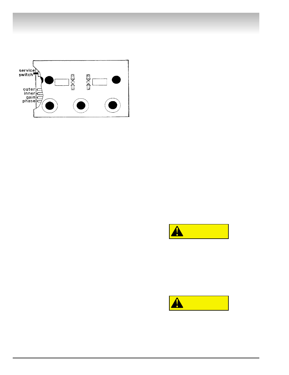
4. Set service switch to upper position (test mode).
Press the START button. The display will now read
“TEST”. The outer and inner position lights will now act
as bar graphs. First adjust the gain trimpot until the
minimum number of lights are on or flashing.
Alternately adjust the gain and phase trimpots until all
the lights are off.
5. Set service switch to bottom position (NORM).
Remove the test weight and then balance the wheel.
A maximum imbalance of .07 ounce (2 gram) on the
inner and outer weight displays is allowed.
6. Place a 4 ounce (113 gram) test weight on the
outer rim.
7. Set the service switch to center position (non-
stop). Press the START button. Wheel will come up to
speed, but not go into braking mode. Now adjust the
outer weight trimpot (affects outer magnitude). After
each adjustment of the trimpot, press and hold the
START button until a new reading appears on the dis-
play. Continue this procedure until the outer weight
display reads 4 ounce (113 gram). The inner weight
reading should be .21 ounce (6 gram) or less. Set the
service, switch to the bottom position so that the
wheel will brake to a stop.
8. Place the 4 ounce (113 gram) test weight on the
inner rim. Set service switch to center position. Press
the START button.
9. Adjust the inner weight trimpot (affects inner
magnitude) until display reads 4 ounce (113 gram). Use
the same procedure as in Step 7. The outer weight
reading should be .21 ounce (6 gram) or less. Set the
service switch to the bottom position (NORM).
10. Calibration is now complete. To return the bal-
ancer to the normal operating mode: Switch off the
power and then turn it on again (On/Off switch located
on rear of machine). This clears the high accuracy
mode and the balancer is ready to use.
Optional Combi Adaptor
Combi adapter may be used for 3, 4, 5, 6, 8, or 10-
Lug wheels by installing swivel plates in Combi plate
hole pattern. Set up adapter as follows:
Install a swivel plate in combi plate “common” hole.
Line up number gear to match “345” mark with index
mark on swivel plate. Insert swivel plate bolt through
back of combi plate and run up. DO NOT TIGHTEN.
Note: This swivel plate is used for all bolt circle pat-
terns.
Install proper number of swivel plates in combi plate
holes marked “3”, “4”, or “5” as required. Insert swivel
plate bolts through back of combi plate and run up, DO
NOT TIGHTEN. Ensure that index marks on all swivel
plates line up with the appropriate “3”, “4”, or “5” mark
on the number gear.
Install combi adapter on wheel Run up lug nuts by
hand. Tighten lug nuts with adapter wrench, using a
star or criss-cross pattern.
Lug nuts must be centered and threaded at
least four full turns Reverse lug nuts as
required. Use only adapter wrench fur-
nished with adapter Do not use air tools or
impact wrenches.
Tighten swivel plate bolts with alien wrench.
Attach wheel and adapter to faceplate with two
faceplate nuts.
Faceplate nuts must be hand tightened.
Rotate wheel while tightening to ensure
centering.
Adapter should remain on faceplate for additional
wheels with same bolt circle.
CAUTION
CAUTION
High Accuracy Mode For Calibration