APG DCR-1004 user manual User Manual
Page 8
DCR-1003 and DCR-1004
Rev. A3, 10/08
8
Automation Products Group, Inc.
APG...Providing tailored solutions for measurement applications
Tel: 1/888/525-7300 • Fax: 1/435/753-7490 • www.apgsensors.com • [email protected]
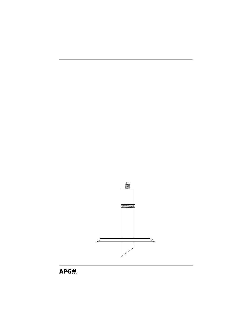
Stand Pipe Mounting
The stand pipe should be as large in diameter and as short in length as
possible. Mount the sensor above the highest anticipated material by at least
the published blanking distance.
The stand pipe should be seamless to provide a smooth path for the sound
waves to propagate into the tank. Because the sound waves will concentrate
along the inside wall of the pipe, any seams from couplers, nipples, and welds
will cause echo returns that will be picked up by the sensor. The sensor
blanking will need to be changed to a distance greater than the length of the
pipe (found on page 15; mode 5).
The end of the stand pipe should extend inside the tank and be cut to a 45°
angle. Make sure that the cut is clean and free from burs. If the standpipe is cut
at 90°, there will develop a standing wave echo at the end of the pipe that will be
seen by the sensor as a target. If a 45° cut is not feasible in your application,
then the cut should be made as close to 45° as possible (often, even a 10° cut
will shrink the standing wave enough to allow the sensor to see past it).
To avoid false Echoes, the stand pipe should be installed where there is a
clear sound path perpendicular to the detection surface and where the sound
path will not intersect vessel fill spouts, rough vessel walls, ladders…etc. Any
angle off perpendicular will degrade the performance of the sensor.
Top of Tank
Stand Pipe
10-45
o
CUT