APG DCR-1004 user manual User Manual
Page 12
DCR-1003 and DCR-1004
Rev. A3, 10/08
12
Automation Products Group, Inc.
APG...Providing tailored solutions for measurement applications
Tel: 1/888/525-7300 • Fax: 1/435/753-7490 • www.apgsensors.com • [email protected]
Step 4: Wires can be pulled into the DCR-1003, 1004 through the strain
reliefs on the enclosure, or the strain reliefs may be removed and 1/2 in.
conduit used in their place.
The spring loaded terminal can be wired using solid or stranded wire
between 16 - 20 AWG. Wires should be stripped, leaving a .4 in. bare wire. The
wires can then be inserted into the terminal by depressing the associated
orange lever with a #5 1/8 in. screwdriver. While the lever is depressed, the
conductor should be pushed into the terminal until it bottoms out. The lever
should then be released, securing the conductor in the terminal.
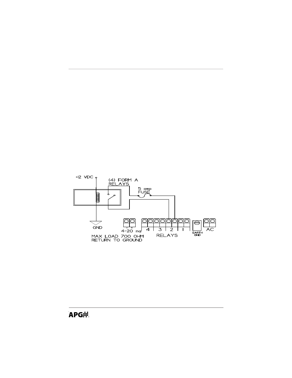
Follow the legend on the circuit board when wiring the DCR. The DCR-
Controller should never be used without the earth ground terminal being
connected.
Step 5: Perform an internal check to ensure that all wires are properly
connected and secured.
Step 6: Close the hinged panel and make the power connection. The LED
display should turn on and the COM light illuminate.