APG DCR-1004 user manual User Manual
Page 24
DCR-1003 and DCR-1004
Rev. A3, 10/08
24
Automation Products Group, Inc.
APG...Providing tailored solutions for measurement applications
Tel: 1/888/525-7300 • Fax: 1/435/753-7490 • www.apgsensors.com • [email protected]
ANALOG
The analog output is only available on controller model DCR-1004. The
analog circuit comes standard with 4-20 mA, but may be configured for 0-20
mA. A hardware change will allow 0-5 V, or 0-10 V as the output.
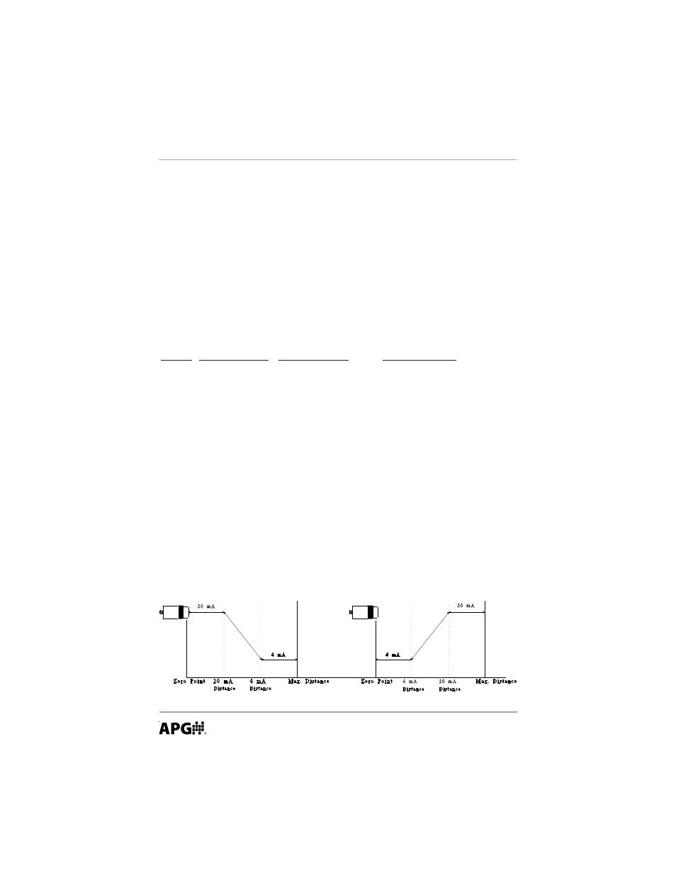
The desired analog output should first be selected in mode 24. The two end
points must then be entered. For performing a distance to level measurement,
the zero point of distance will be at the transducer and the 4-20 limits will be
programmed in the same units as mode 1. For volumetric or open channel
monitoring, the zero point will be at the empty point of the tank or flume and
the end points must be set in the units used in the volume or flow measurement.
Keep this in mind when referring to the diagram below.
MODE DESCRIPTION
PARAMETERS
EXPLANATION
24
Analog Output
Range = 0 - 1
Selects the type of analog output
Select
0 = 4 to 20mA
output to be used
1 = 0 to 20mA
Set by NUM UP or NUM DN
Default = 0
25
0,4 mA Distance
Units = mode 1
Sets the minimum distance of
Default = 3.00 ft.
the analog output slope
26
20 mA Distance
Units = mode 1
Sets the maximum distance of
Default = 4.00 ft.
the analog output slope
27
0,4 mA Calibration
Fine tunes the minimum current
sourced on the analog output
28
20 mA Calibration
Fine tunes the maximum current
sourced on the analog output