APG DCR-1004 user manual User Manual
Page 11
Rev. A3, 10/08
DCR-1003 and DCR-1004
11
Automation Products Group, Inc.
APG...Providing tailored solutions for measurement applications
Tel: 1/888/525-7300 • Fax: 1/435/753-7490 • www.apgsensors.com • [email protected]
• Wiring
Step 1: Connect the DST to the DCR Controller using RG-6 coaxial cable
with ‘F’ series connectors. If more than one DST is to be connected for a
differential application, the two sensors should be connected to the DCR using
an external splitter.
Step 2: To obtain access to the DCR’S terminal strip, open the DCR’s
plexiglass cover and raise the hinged panel by loosening the knurled thumb
screws.
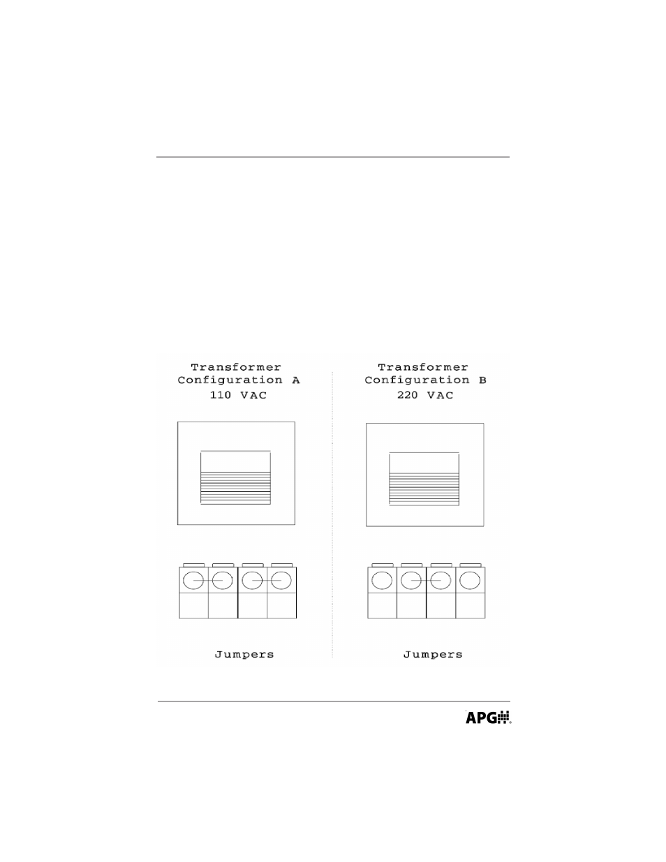
Step 3: The DCR-1003, 1004 is shipped from the factory configured for 100-
120 VAC input power. If 200-230 VAC is to be used, change the jumpers
configuration to 220 VAC as shown in the diagram below.