Brake lathes, Warning, Rotor drive unit operation – AMMCO 700 Vehicle Brake Lathe User Manual
Page 21
Rotor Drive Unit Operation
The Rotor Driving Unit provides the power source to turn the
rotors. This unit was designed for use with the Vehicle Mounted
Brake Lathe.
The driving unit will provide a constant rotation, can be
adjusted to suit various lift heights, and will adapt to the various
lug bolt configurations.
After the vehicle has been prepped, and the lathe has been
mounted (see VEHICLE PREPARATION AND LATHE MOUNT-
ING PROCEDURES). Mount the lug adapter to the rotor hub
(see MOUNTING OF LUG ADAPTER).
The driving unit may now be rolled into position.
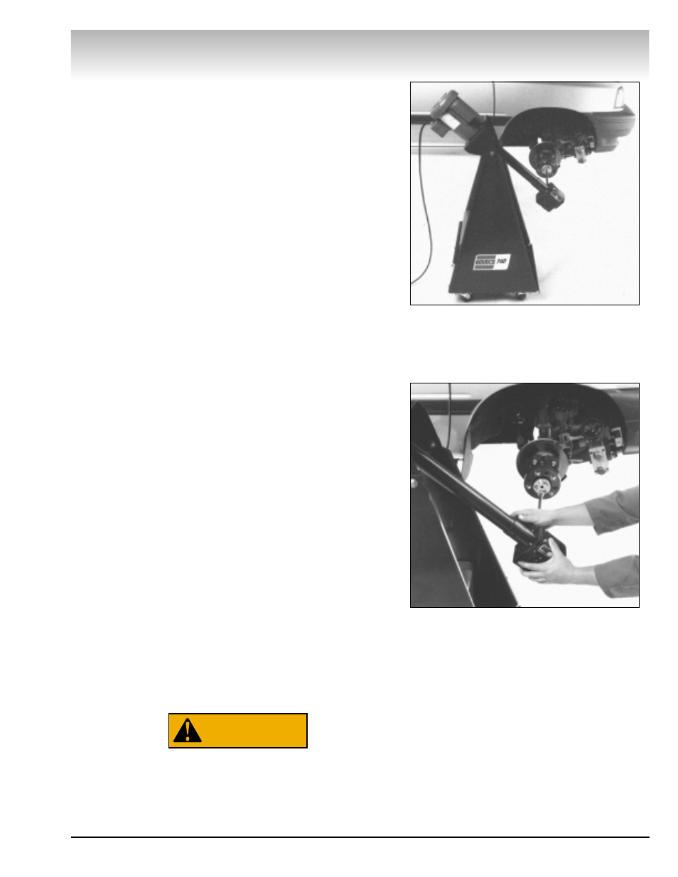
1. Select a convenient position for the driving unit floor stand.
For example, if the lathe is located on the front side of the axle,
it may be cumbersome to locate the floor stand on the same
side, Fig. 29.
Using the vehicle’s lug nuts, loosely tighten the lug adapter to
the rotor hub. Check to see that EACH lug nut’s taper seats in
the bevel in the leg. When all nuts am properly seated, tighten
lug nuts to approximately 30 ft. lbs.
Note: If the wheels must be turned at an angle to mount the
lathe, it may be necessary to locate the floor stand on the same
side to avoid contact with the vehicle.
2. Pivot the motor/gearbox unit to align the drive shaft with its
mating hole in the lug adapter plate.
Using the vehicle’s lug nuts, loosely tighten the lug adapter to
the rotor hub. Check to see that EACH lug nut’s taper seats in
the bevel in the leg. When all nuts am properly seated, tighten
lug nuts to approximately 30 ft. lbs.
Pivot the motor/gearbox unit to align the drive shaft with its
mating hole in the lug adapter plate.
3. Loosen the knob securing the gearbox to the motor tube,
and rotate the gearbox end drive shaft to an approximate right
angle position relative to the tilt of the rotor, Fig. 30
4. Move the entire unit towards the vehicle, and align the
square shaft with the adapter. Push the square shaft thru the
adapter.
5. Adjust gearbox to insure drive shaft is as straight as possi-
ble.
6. Double check that vehicle is placed in “Neutral” gear.
Serious damage to the Rotor Driving Unit may result
if the vehicle is not in "Neutral" gear.
7. Plug driving unit into an approved 115 VAC or 230VAC
power source, refer to ELECTRICAL WIRING REQUIREMENTS.
WARNING
Brake Lathes
AMMCO 700/705/710 Brake Lathes • 15
Figure 29
Figure 30