Brake lathes – AMMCO 700 Vehicle Brake Lathe User Manual
Page 13
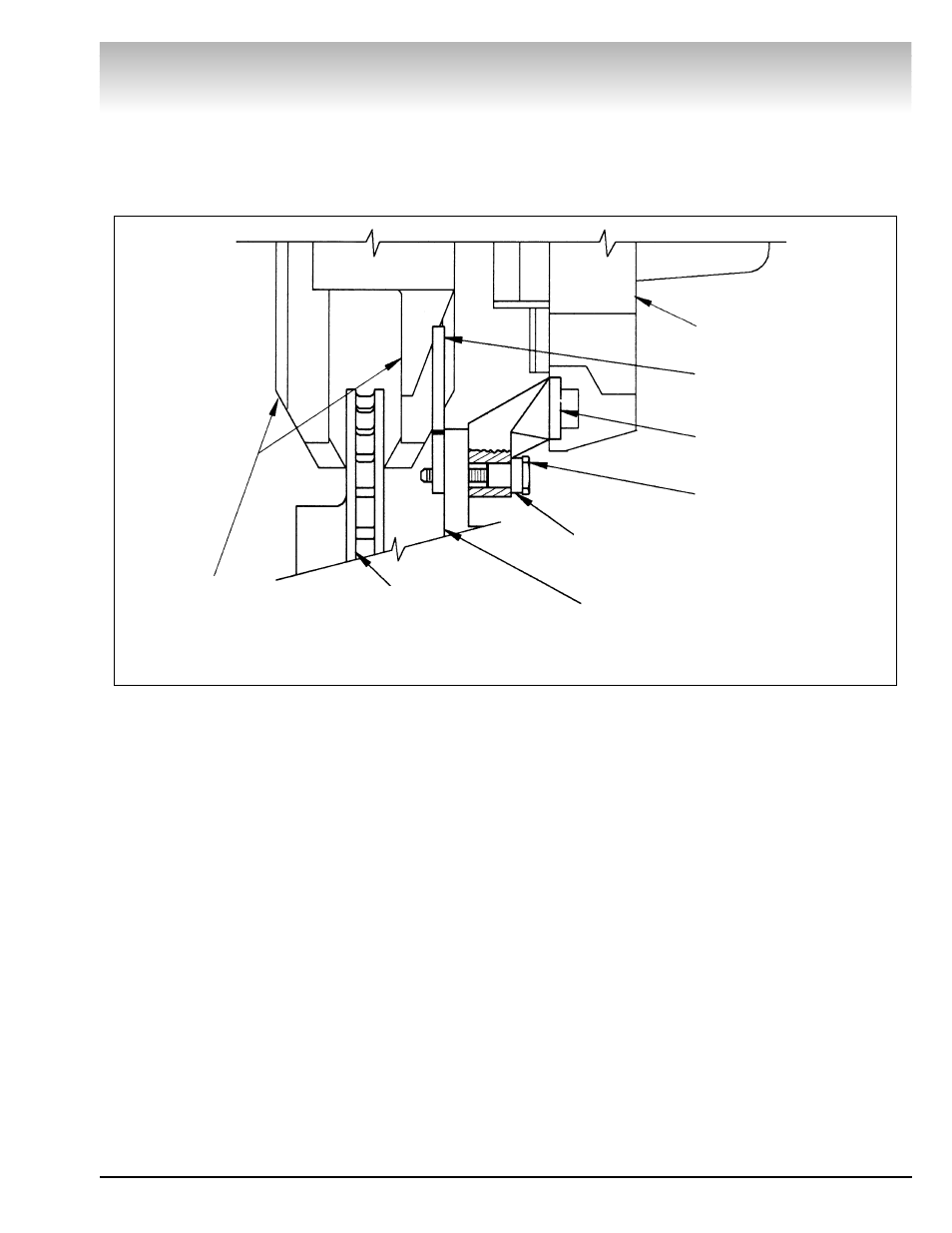
Installation With Mounting Bolts Supplied in
Mounting Hardware
Note: Use Figure 11 to assist during installation of the brake
lathe when using the mounting bolts supplied with the mount-
ing hardware.
1. Place spacer(s), as required, onto the mounting bolt.
2. Insert the mounting bolt with spacers into the upper lathe
mounting bracket.
3. Lift the lathe and align the upper mounting bolt with the
upper caliper bracket bolt hole. Insert the bolt through the
caliper bracket.
4. Place a nut plate between the upper caliper bracket and the
rotor. Finger tighten the mounting bolt into the nut plate. Let the
lathe hang down.
5. Make sure the mounting bolt does not interfere with the
rotor. If necessary, remove the bolt and add spacers.
6. Adjust the lathe mounting brackets, Fig. 10 on the previous
page, until the lower lathe mounting bracket aligns with the
lower caliper bracket bolt hole.
7. Repeat steps 1 thru 5 to install the lower mounting bolt.
8. Torque the mounting bolts to 15 foot pounds.
Brake Lathes
AMMCO 700/705/710 Brake Lathes • 7
Figure 11
Lathe Frame
Mounting Bolt
Lathe Mounting
Bracket
Nut Plate
Spacer
(If Needed)
Inboard Caliper
Mounting Bracket
Rotor
Lathe Cutting
Arms