Brake lathes, Electrical wiring requirements, Assembly instructions – AMMCO 700 Vehicle Brake Lathe User Manual
Page 19
AMMCO 700/705/710 Brake Lathes • 13
Electrical Wiring
Requirements
The driving unit should be electrically grounded to pro-
tect the operator from shock. The unit is equipped with
an approved 3-conductor cord and a 3-prong grounding
type plug to fit the proper grounding type receptacle. If
your unit is for use on 115 volts, it has a plug and outlet
as illustrated in Fig. 22. Use only 3-wire extension cords
which have 3-prong grounding type plugs and 3-pole
receptacles which accept the unit’s plug. 230 volt units
use a plug and outlet like those illustrated in Fig. 23.
Any line voltage lower or higher than ten percent
(10%) of nominal will cause problems with the machine.
If the machine receives below or above the design limit,
erratic operation will ensue with a degradation in com-
ponent reliability and life. By law the power company
must supply power within the ten percent (10%) limit of
nominal line. It is up to the customer to see that his
facility is properly wired and is supplying power to the
machine within its design limits. Inadequate voltages
and wiring will only produce problems.
AMMCO electrical and electronic based machines are
designed for nominal line voltages with variations of ten
percent (10%) around the nominal, i.e.; 115 volt input
could vary from 103 volts on the low side to 127 volts
on the high side. These percentages also apply to 230
VAC based products.
Replace or repair damaged or worn cords immediately.
Thermal Overload Circuit Breaker
The driving unit is equipped with a thermal overload
circuit breaker, it is located in the ON/OFF switch. If the
drive unit’s function is interrupted due to an overload,
this switch has to be reset.
1. Turn the switch to the OFF position.
2. Unplug the drive unit from the power source.
3. Allow 10-15 minutes for the unit to cool down.
4. Make sure the cause of the overload is located and
eliminated.
5. Plug drive unit back into power source.
6. Reset circuit breaker.
Assembly Instructions
The rotor driving unit contains three (3) main assem-
blies. They are:
1. Floor Stand
2. Motor/Gearbox Unit
3. Lug Adapter Set
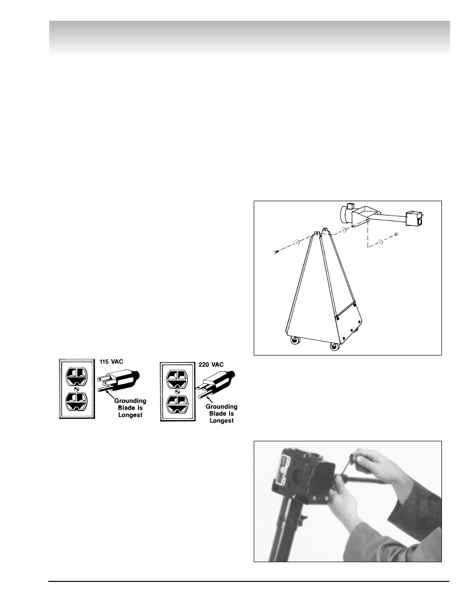
1. Center the motor/gearbox assembly between the
uprights of the floor stand. Align the holes in the motor
bracket with the holes in the uprights. From the outside,
insert a bolt and washer through the holes. Add a
washer between the upright and motor/gearbox unit,
then slide a washer and locknut over the bolt on the
inside of the floor stand. Repeat on the opposite side,
Fig. 24.
2. Tighten the motor bracket bolts until the
motor/gearbox assembly will hold steady in any position
it is rotated to.
3. Slide the drive shaft over the end of the gearbox
output shaft. tighten the two (2) set screws to securely
hold the shaft in place, Fig. 25.
Brake Lathes
Figure 24
Figure 25
Figure 23
Figure 22