Brake lathes – AMMCO 700 Vehicle Brake Lathe User Manual
Page 15
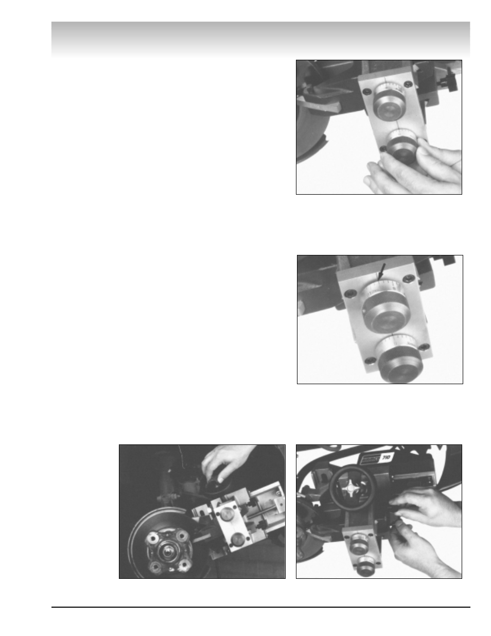
10. Turn the (blue) depth-of-cut knob clockwise to advance
the outboard cutter until it lightly contacts the brake surface.
Holding the knob still, rotate the micrometer dial to zero, Fig. 16.
11. Turn the (red) depth-of-cut knob clockwise to advance the
inboard cutter until it lightly contacts the brake surface. Holding
the knob still, rotate the micrometer dial to zero.
Note: Once you have zeroed a dial, never use the dial microm-
eter to advance or withdraw a cutting bit; the dial may slip, los-
ing the zero position. Use the depth-of-cut knob to advance or
withdraw the cutting bit.
12. Advance the carriage with the handwheel until the out-
board cutting bit reaches the inside edge of the braking surface
of the rotor.
13. Turn the depth-of-cut knobs individually to set each cut-
ting bit to the desired depth-of-cut (usually .006" per side or
three divisions of the micrometer), Fig. 17.
Note: A .006" depth-of-cut per side (a total of .012") will recon-
dition most rotors, although some severely grooved rotors may
require more than one cut.
Cuts may be .002" -- .010" deep.
14. Tighten the cutter locking knobs, Fig. 18.
15. Tighten the engagement knob in the center of the hand-
wheel, Fig. 19. This will start the cut. When the cutting bits have
cleared the outer edge of the rotor, loosen the engagement
knob to stop the carriage.
16. Turn off the Rotor Driving Unit and inspect both surfaces
of the rotor.
17. If part of the brake surface was not cut, leave the cutters
locked in position. Turn on the Rotor Driving Unit. Slowly turn the
handwheel to move the carriage to the inside edge of the brak-
ing surface.
18. Repeat steps 13, 14, 15, and 16.
Brake Lathes
AMMCO 700/705/710 Brake Lathes • 9
Figure 16
Figure 17
Figure 18
Figure 19