Terminal description (newer hw), Terminals, Installation – compact version 2.6 – 2N Lift emergency phone 2N SingleTalk - Manual, 1514 v6.3.0 User Manual
Page 37
Installation
– Compact Version
2.6
36
Terminal Description (newer HW)
Tip
The above mentioned safety precautions need not be observed in case
your ST unit is connected to a 2N® EasyGate GSM gateway installed near
the communicator.
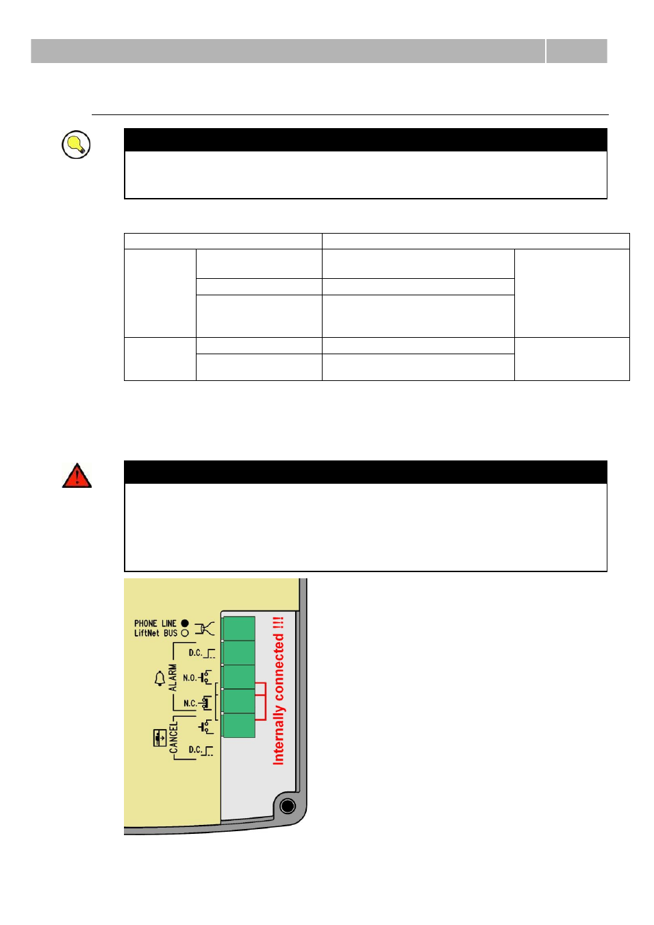
Terminals
Telephone line / LN bus
Refer to ST or LN User Manual
ALARM
terminals
DC = voltage
control *)
5 – 24Vdc, any polarity
Emergency call
activation
N.O. = N/O contact normally open contact
N.C. = N/C contact Normally closed contact
WARNING! If unused, the
contact should not be opened!
CANCEL
terminal
voltage control *)
5 – 24Vdc, any polarity **)
Emergency call
deactivation upon
door opening
contact control
any contact **)
*) For safety reasons, these terminals are electrically isolated from the telephone line.
**) You need not do anything to activate ALARM if you keep the factory settings. For
deactivation, voltage application or contact closing is necessary. To change the
settings use parameter 916 for ST and the rotary switch for LN.
Accident Hazard
Make sure that the button is safe, i.e. that the minimum isolation distance
is 1.5 mm and the minimum breakdown voltage value is 1,500 V. The
button contacts may not be connected to any other circuits. If any of the
above conditions cannot be met, use voltage control.
You can use an N/O or N/C button or both.
Refer to the rear cover for internally connected terminals.