Jumper settings, Connectors accessible after cover removal, Installation – universal version 2.5 – 2N Lift emergency phone 2N SingleTalk - Manual, 1514 v6.3.0 User Manual
Page 28
Installation
– universal version
2.5
27
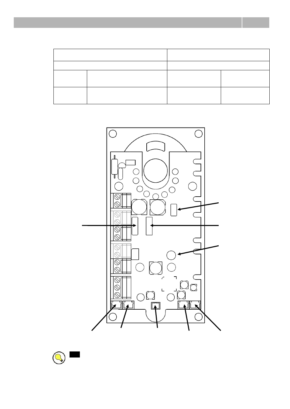
Jumper Settings
Left-hand jumper (ALARM INPUT)
Right-hand jumper (PROGRAMMING)
inverted ALARM input
disabled PROGRAMMING
up
(NORMAL)
closing contact or voltage
connection activation
up
(ENABLED)
enabled
down
(NEG.)
breaking contact or voltage
disconnection activation
down
(DISABLED)
disabled
Connectors accessible after cover removal
servicing
connector
(do not
connect
anything)
servicing connector
(button 2 can be
connected to two
bottom contacts )
extending module
connector
extending module
mounting spacer
"Wait" LED
connector
“Connection
established”
LED" connector
External
microphone
connector
Loudspeaker
connector
Induction
loop
connector
Tip:
To access connectors at the bottom edge of the board without cover
removal, just loosen cover screws gently and slide the cover upward. Applies to
HW version 7 and higher, when amplifier module is not mounted.
- Analogue GSM gateway 2N EasyGate - Manual, 1575 v1.1.0.2 (69 pages)
- Fixed line replacement with 2N EasyGate - Quick Start, 1129 v1.5E (2 pages)
- Fixed line replacement with 2N EasyGate PRO - Quick Start, 1711 v1.01 (2 pages)
- Analogue GSM gateway 2N EasyGate PRO - Manual, 1749 v1.03 (79 pages)
- Fixed line replacement with 2N EasyGate PRO UMTS - Quick Start, 2018 v1.00 (2 pages)
- Analogue UMTS gateway 2N EasyGate UMTS USB - Quick Start (9 pages)
- Analogue UMTS gateway 2N EasyGate UMTS USB - User Manual, v1.00 (38 pages)
- Wireless 3G router 2N EasyRoute_old design - Quick start, 1526 v2.00 (2 pages)
- Wireless 3G router 2N EasyRoute_new design - Quick start, 1664 v1.00 (2 pages)
- Wireless 3G router 2N EasyRoute_new design - User manual, 1670 v1.06 (101 pages)
- Wireless 3G router 2N EasyRoute_old design - User manual, 1571 v1.06 (99 pages)
- Entrance guard 2N Helios - Manual - antivandal installation (2 pages)
- Design intercom 2N Helios - Guide mounting (2 pages)
- Door camera for 2N Helios - Installation manual - camera 9135210E (2 pages)
- Home intercom 2N Helios - Manual - display installation (5 pages)
- Electric lock for 2N Helios - Secondary switch - installation manual, 1360 v2.0 (2 pages)
- Door intercom 2N Helios - Manual, 1322 v3.0 (76 pages)
- Helios IP User manual, 1510 v1.13 (143 pages)
- Helios IP User manual, 1510 v1.12 (127 pages)
- Helios IP User manual, 1510 v1.11 (119 pages)
- Lift emergency phone 2N LiftNet - Manual, 1446 v1.8.3 (97 pages)
- Mobile Audio Gateway public address system - Quick start manual (2 pages)
- IVR Editor manual v1.0.2 (43 pages)
- Omega Lite PBX Assistant - manual v1.2 (57 pages)
- Omega series - Configuration Tool manual v1.10 (114 pages)
- IVR Editor manual v1.0 (43 pages)
- Omega series - Configuration Tool manual v1.9 (114 pages)
- Omega series - VoIP manual v1.4 (113 pages)
- Omega 48 - Basic Services v1.0 (60 pages)
- Omega 48 - Installation Manual v1.0 (48 pages)
- Omega 48 - Operator Services v1.0 (48 pages)
- StarPoint 500 - manual v2.0 (32 pages)
- Omega Lite - Configuration Tool manual v1.6 (101 pages)
- Omega Series - Voicemail v1.0 (31 pages)
- Omega Lite - Installation Manual v1.9 (58 pages)
- Omega Lite - Configuration Tool manual v1.8 (112 pages)
- Omega Lite - Configuration Tool manual v1.7 (112 pages)
- Omega Series - Basic Services (60 pages)
- Omega Lite - Installation Manual v1.5 (53 pages)
- Omega Series - Operator Services (48 pages)
- Omega Lite Panel - manual v1.0 (34 pages)
- Omega Lite PBX Assistant - manual v1.0 (49 pages)
- Omega Lite - Quick Guide v1.0 (1 page)
- Omega Series - VoIP manual v1.2 (88 pages)