1 description, Description 2.1 – 2N Analogue GSM gateway 2N EasyGate PRO - Manual, 1749 v1.03 User Manual
Page 14
Description
2.1
14
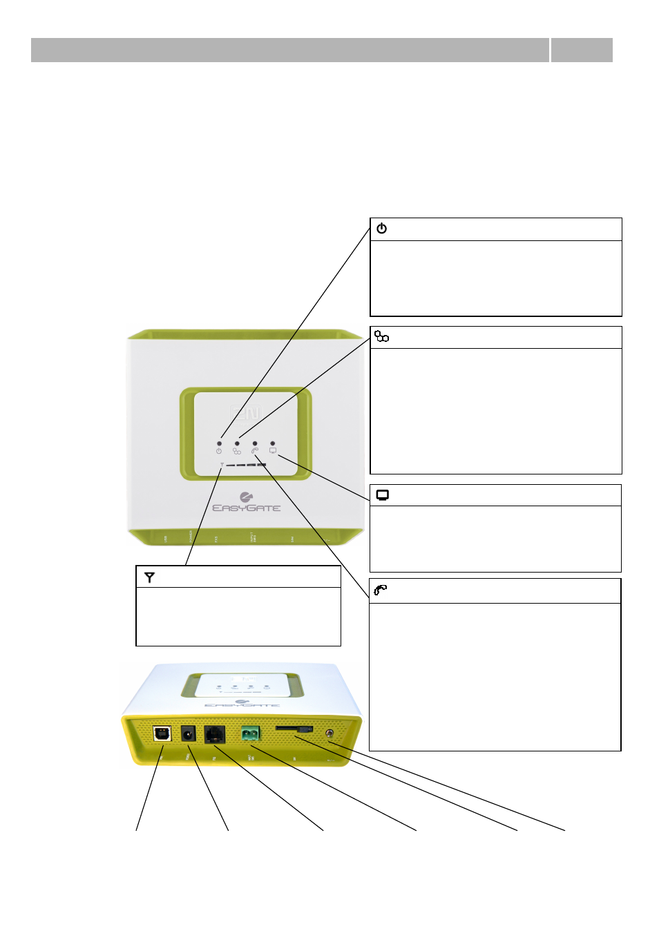
2.1 Description
EasyGate consites of GSM (UMTS) gateway in white plastic cover, removable antenna
and cables for connecting to phone set and PC
2N
®
EasyGate ’s status is indicated by LED diodes on its front side. All possible states
are described in the following figure.
USB
(USB 2.0)
Power supply
connector
(DC Jack 2.1 mm,
internal contact +)
Telephone
line
(RJ 12, 6/2)
SMS connector
(SMS sending input)
SIM
Switch
(ON/OFF)
Figure 2.2
EasyGate
Connectors
Figure 2.1
EasyGate LED
indicators
No light
Standby
Flashes quickly line off-hook or ringing
Lights yellow
call FXS – GSM (UMTS)
Fax models only:
Flashes 2x then pause
Fax or modem connection in
progress; after power on
signalizes need of FW upgrade
Flashes 3x then pause
fax or modem connection in
progress
Telephone line
Lights blue
device is powered from the grid.
Lights yellow
device is powered from the
battery.
Flashes 1x in 2s HW error, contact the
manufacturer
No light
Power switched off or HW error
Power supply
Lights blue
Registered to GSM (UMTS)
Flashes:
1x in 1s
not registered, SIM card inserted
1x in 3s
not registered,
SIM card not inserted
4x quickly
enter your PIN
8x quickly
enter your PUK (use mobile
phone)
Quickly and continuously
All functions are blocked. Your SIM doesn’t
correspond to the operator lock.
Mobile network
Lights green
PC connected
Flashes:
Quickly
incoming data call (CSD)
1x in 3s
data connection (CSD or GPRS)
No light
PC not connected
Data – PC connection status
Steady state – signalization of signal
strength
FXS line off hook – signalization of
battery state (battery backup type only)
Signal strength/battery indicator