8 air cleaner assembly, 1 air cleaner assembly removal, 2 air cleaner assembly installation – JLG 4017 Service Manual User Manual
Page 95: 9 engine replacement, 1 engine removal, Air cleaner assembly, Engine replacement, Air cleaner assembly removal, Air cleaner assembly installation, Engine removal
7.9
4017
Engine: Perkins 1004-40T
3. Install the muffler to the exhaust pipe and bolt the
muffler to the side of the frame.
4. Install the clamp securing the muffler to the exhaust
pipe.
5. Install the clamp securing the muffler to the tail pipe.
6. Adjust the muffler, exhaust and tail pipes for proper
clearance then tighten all clamps.
7. Connect the negative (-) battery cable to the negative (-)
battery terminal.
8. Start engine and check for exhaust leaks at all
exhaust connections. Adjust or repair as needed.
9. Install the belly pan.
7.8
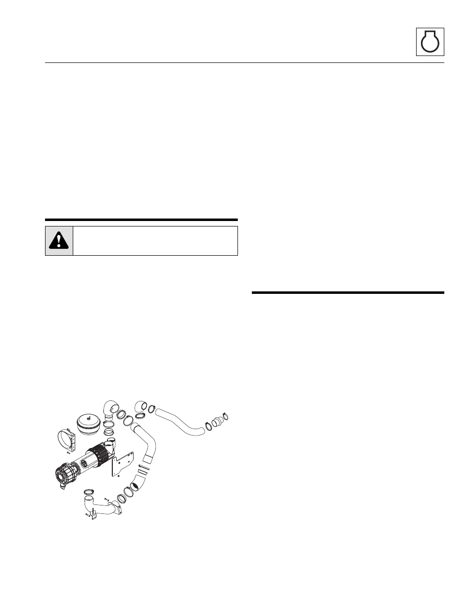
AIR CLEANER ASSEMBLY
IMPORTANT: Refer to the appropriate Operator &
Safety Manual for your machine for the correct element
change procedure.
7.8.1
Air Cleaner Assembly Removal
1. Open the engine cover.
2. Disconnect low pressure indicator wire connection.
3. Remove the clamp securing the air intake elbow to
the air cleaner assembly. Lift the air intake elbow off
the air cleaner.
4. The reducing insert and the reinforcement ring
should be removed along with the air intake tube.
5. Remove the clamp securing the air outlet elbow. Lift
the air outlet elbow off the air cleaner.
6. Remove the two capscrews and ripp nuts securing
the air cleaner mounting bracket to the air cleaner
mounting plate. Remove the air cleaner assembly.
7.8.2
Air Cleaner Assembly Installation
Note: Apply Loctite
®
242 threadlock to the capscrew
threads before installation.
1. With the air cleaner assembly attached, install the air
cleaner mounting bracket using capscrews and ripp
nuts.
2. Place the loosened clamps over the air intake elbow
along with the reducing insert and the reinforcement
ring, and install elbow on the air cleaner assembly.
3. Place the loosened clamps over the air outlet elbow
and install elbow on the air cleaner assembly.
4. Connect low pressure indicator wire connection.
5. Adjust and tighten both clamps before starting the
machine.
6. Close and secure the engine cover.
7.9
ENGINE REPLACEMENT
7.9.1
Engine Removal
Note: The radiator and oil cooler must be removed from
the machine before engine removal. Refer to
7.4, “Engine Cooling System.” Several additional
components must be removed before engine removal.
They will be addressed in the following procedures.
1. Park the machine on a firm, level surface, fully
retract the boom, lower the boom, place the
transmission control lever in NEUTRAL (N), engage
the park brake and shut off the engine.
2. Place an Accident Prevention Tag on both the
ignition key switch and the steering wheel, stating
that the machine should not be operated.
3. Open the engine cover. Allow the system fluids to
cool.
Note: ALWAYS replace elastic locknuts with new elastic
locknuts to help ensure proper fastening.
4. Remove the engine cover, radiator guard plate and
the engine belly pan.
5. Remove the radiator overflow bottle and hoses.
6. Refer to Section 7.4.3, “Radiator/Oil Cooler and
Replacement,” to remove the radiator/oil cooler.
7. Loosen the clamps on each heater hose on the
engine. Plug the heater hoses if necessary.
CAUTION:
NEVER run the engine with
only the inner safety element installed.
MZ0120