5 windshield wiper assembly, 6 heater/defroster system, Windshield wiper assembly – JLG 4017 Service Manual User Manual
Page 58: Heater/defroster system
Cab and Covers
4.6
4017
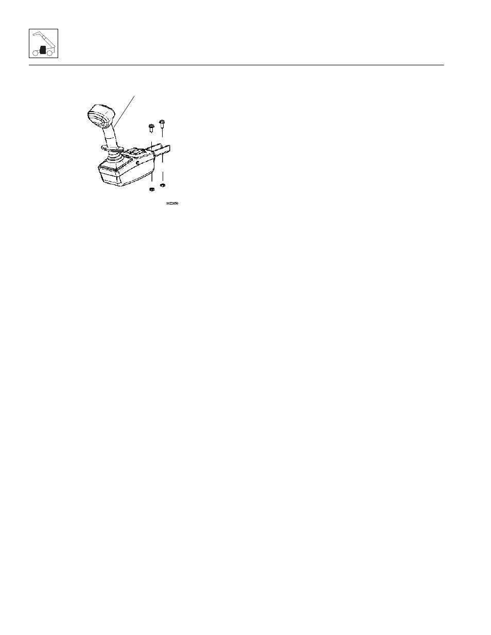
b. Joystick Assembly Installation
1. Set the joystick assembly (1) into the armrest
support.
2. Install the four self-tapping screws. Connect the
electrical connections.
3. Test the boom extend/retract and boom lift/lower
joystick function:
a. Move the joystick handle rearward, activating the
boom lift function. The boom should RISE.
b. Move the joystick handle forward, activating the
boom lower function. The boom should LOWER.
c. Move the joystick handle to the right, activating
the boom extend function. The boom should
EXTEND.
d. Move the joystick handle to the left, activating the
boom retract function. The boom should
RETRACT.
4. Install the bottom cover and secure using two lens-
head capscrews.
5. Close and secure the engine cover.
Refer to Section 9.13, “Joystick,” for complete joystick
functions.
4.3.5
Windshield Wiper Assembly
Refer to Section 9.9, “Window Wiper/Washer Windshield
Wiper Motor,” for removal and installation information.
4.3.6
Heater/Defroster System
a. Heater Assembly Removal
1. Park the machine on a firm, level surface, fully
retract the boom, lower the boom, place the
transmission control lever in the (N) NEUTRAL,
engage the park brake and shut the engine OFF.
2. Place an Accident Prevention Tag on both the
ignition key switch and the steering wheel, stating
that the machine should not be operated.
3. Open the engine cover. Allow the system fluids to
cool. Draining the cooling system while the engine
block is hot can cause cracks in the engine block.
4. Remove the battery negative (-) cable from the
battery negative (-) terminal.
5. Remove the eight bolts holding the engine belly pan
and remove the belly pan.
6. Refer to Section 7.4, “Engine Cooling System,” for
proper coolant draining.
7. Transfer the coolant to a container with a cover, and
label as “Used Antifreeze.” Dispose of the used
coolant at an approved recycling facility.
Note: Label all hoses to ensure correct installation.
8. Remove the six ripp bolts and remove the cab
bottom shield.
9. Label, disconnect and cap the two heater hoses.
10. Remove the heat duct hoses from back side of the
heating unit assembly.
11. Carefully lower the heater assembly (2) by hand.
Label and disconnect the wiring harness
connections at the blower.
12. Remove the heater assembly.
1