2 service warnings, 1 electronics, 3 specifications – JLG 4017 Service Manual User Manual
Page 124: 4 fuses and relays, 1 fuse and relay locations, Service warnings, Specifications, Fuses and relays, Electronics, Fuse and relay locations
Electrical System
9.4
4017
9.2
SERVICE WARNINGS
9.2.1
Electronics
9.3
SPECIFICATIONS
Electrical system specifications are listed in Section 2,
“General Information and Specifications.”
9.4
FUSES AND RELAYS
9.4.1
Fuse and Relay Locations
a. Cab
For access to the fuse and relay panel, remove the four
screws securing the right side console access panel to
the cab. The fuses and sealed 12-volt relays are mounted
under the right side console access panel. The fuse and
relay panels are part of the cab harness.
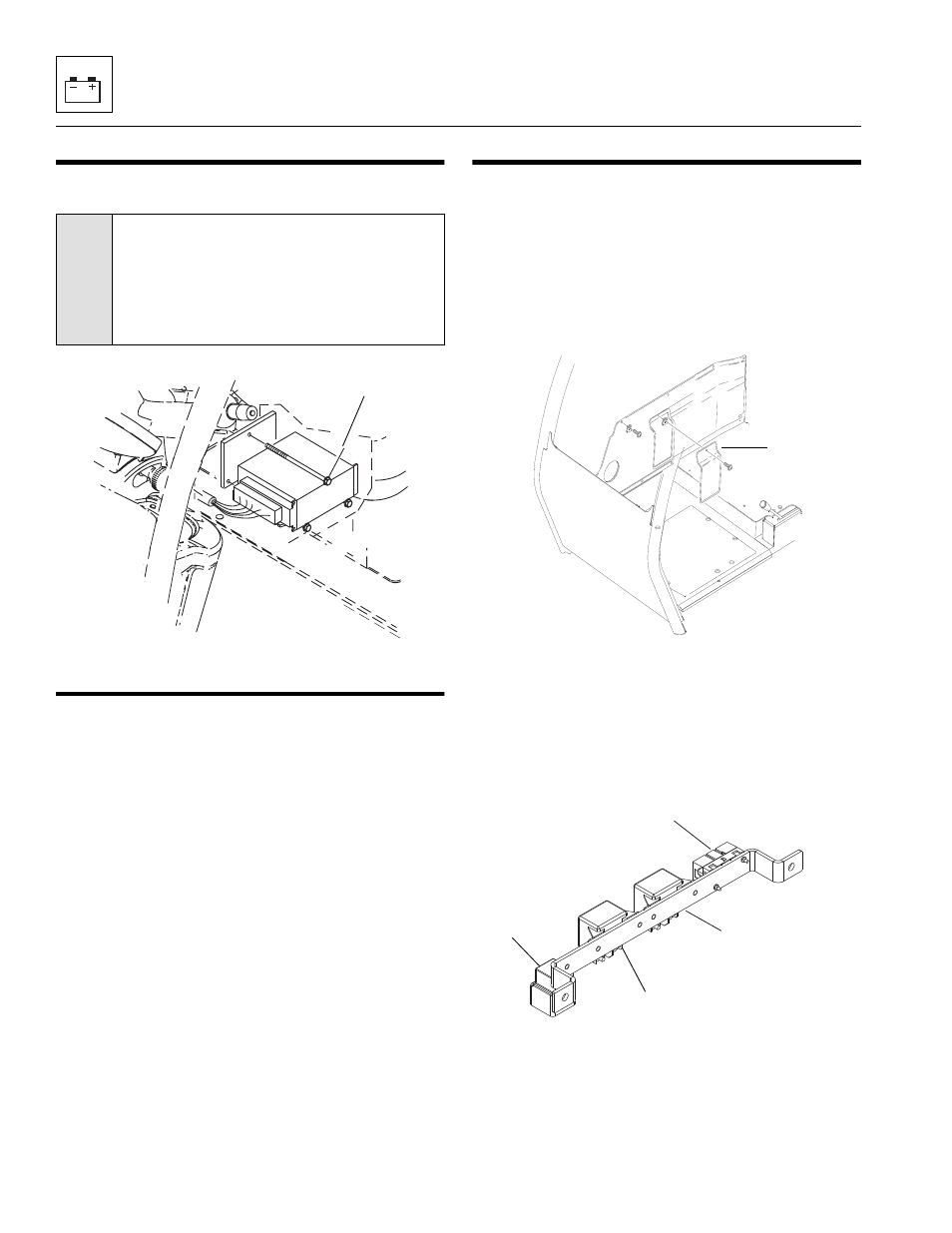
b. Engine Compartment
The fuse and relay bar is located on the frame directly
above the engine. To remove the relays from inside the
engine compartment, remove the mounting screws and
washers. When re-installing the relays torque the
mounting hardware to 7 - 12,5 Nm (62 - 110 lb -in).
CAUTION:
When doing welding
anywhere on the machine disconnect the wire
harness from the ESX Control Module
mounted under the operators seat and
disconnect both cables from the battery and
clamp both cables together.
MZ0520
ESX Control Module
MZ1070
Fuse Cover
MZ0540
Lift Pump
Relay
(Included W/
Cable)
Glow Plug
Relay
Starter Relay
Lift Pump & Glow Plug
Fuses